Plan the TV signal chain in this order: antenna, antenna mast, outdoor connector, coax cable, indoor connector, coax splitter if needed, and television input. Use RG6 cable for most residential runs, keep the path as short and simple as practical, and test each section before replacing the antenna. A coax cable tester can find opens, shorts, and some wiring mistakes, but it cannot measure broadcast signal strength.
For a weak or missing station, isolate the system from the antenna toward the TV. First verify the antenna and connections, then test the cable run, bypass the splitter, and use a live signal measurement or channel scan to distinguish cable faults from poor VHF or UHF reception.
From the antenna mast to the television input: map the complete signal path
Draw the complete route before troubleshooting. The antenna receives radio-frequency broadcasts, including VHF and UHF channels. The antenna mast supports and positions it above nearby obstructions; it does not improve a signal simply because it is taller, although height and a clear direction can improve reception. The antenna should be securely mounted and its outdoor metalwork grounded according to applicable electrical requirements.
From the antenna, the signal normally travels through these points:
- Antenna: Converts incoming broadcast energy into an electrical signal at its terminals. Its design and orientation affect VHF and UHF reception differently.
- Antenna mast and mount: Hold the antenna steady and establish its position. Movement, corrosion, or a loose mount can cause intermittent reception.
- Balun or matching transformer: Many antennas use a 300-ohm twin-lead connection at the antenna and convert it to a 75-ohm coaxial connection.
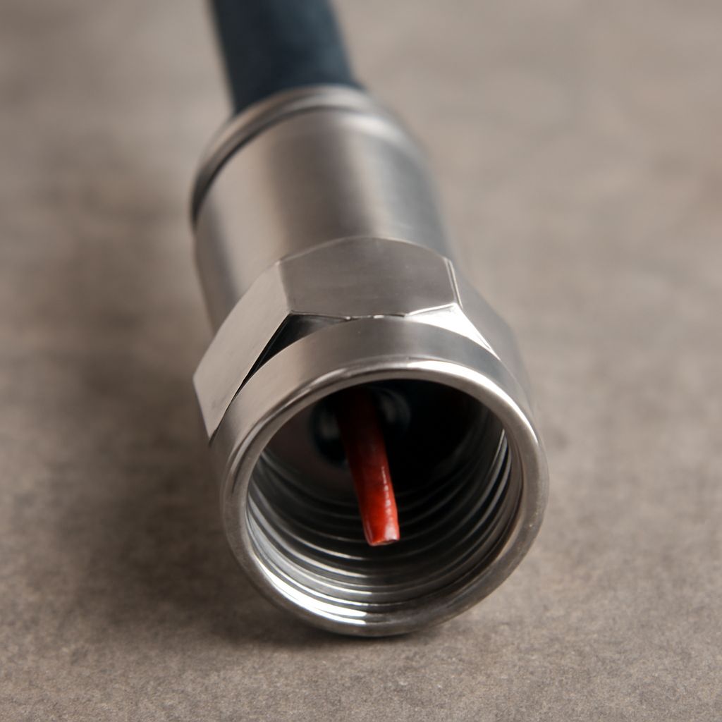
- Outdoor coax connector: Transfers the signal into the cable. It must be weather-resistant, properly fitted, and protected from moisture.
- Coax cable: Carries the 75-ohm signal from the antenna to the building. Each length, bend, splice, and damaged section can add loss.
- Coax splitter: Divides one input among two or more outputs. Every unused output should be terminated with a suitable 75-ohm terminator rather than left exposed.
- Television or tuner: Supplies the final receiver and reports the result as channel lock, picture quality, or a signal meter reading.
Label both ends of every cable and record where each splitter output goes. A direct antenna-to-TV route is the best reference connection. If the system includes an amplifier, inserter, wall plate, grounding block, or several splitters, add each device to the map because each is another possible fault or loss point.
Why RG6 cable is the usual choice for VHF and UHF reception
RG6 cable is the normal choice for over-the-air television because its 75-ohm impedance matches common antenna and television inputs, and its larger center conductor and dielectric generally provide lower loss than RG59 over typical household distances. Choose solid-copper or copper-clad-steel RG6 from a reputable manufacturer with a shield suitable for outdoor use. Quad-shield construction can help with interference, but it does not automatically provide a stronger broadcast signal.
Cable loss increases with length and frequency. A short run may have little practical effect, while a long attic or exterior run can remove enough margin to make a marginal station fail. UHF usually experiences more cable loss than lower-frequency VHF. As a planning estimate, many RG6 products lose roughly 1.5 to 2 dB per 100 feet around lower television frequencies and roughly 5 to 7 dB per 100 feet near 1 GHz; check the manufacturer’s specification for the exact cable.
VHF reception also deserves separate attention. A cable can pass both bands correctly while the antenna is poorly suited to low-VHF or high-VHF channels. Check the station’s actual broadcast band and antenna specifications before blaming the coax. Keep the cable away from sharp kinks, crushing, high-current power wiring, and unnecessary coils. Do not use a damaged cable simply because a continuity test passes: the shield may be compromised, the connector may admit water, or the cable may have excessive high-frequency loss.
How connectors and a coax splitter reduce signal level
A properly installed compression connector introduces very little loss. The larger risk is an intermittent or mismatched connection: a center conductor that is too short, braid strands touching the center pin, a loose F-connector, corrosion, or water inside the cable. These defects can create an open circuit, a short circuit, or a frequency-dependent loss that a basic continuity check may not reveal.
A coax splitter creates predictable insertion loss because its input power is divided among its outputs. A typical two-way splitter loses about 3.5 to 4 dB per output, rather than the ideal 3 dB. A four-way model commonly loses about 7 to 8 dB per output. Three-way splitters vary because some use an unequal division, so read the printed loss values. The loss applies even when only one output is connected.
Use the fewest splitters possible and select one rated for the complete television frequency range, including the UHF band. Do not assume a splitter marked for older cable television service is ideal for every antenna installation. If a splitter must remain, compare the direct path with the split path. A powered distribution amplifier can restore level after a split, but it cannot repair a bad connector, overcome severe antenna misalignment, or recreate signal quality lost to interference. An amplifier placed before a major splitter is usually more useful than one placed after a long, already damaged run.
Wall plates, barrel couplers, surge protectors, and extra adapters also add connection points. Each may work correctly, but temporarily removing them is an efficient diagnostic step.
How to use a coax cable tester—and when to measure live signal
A basic coax cable tester checks the cable’s electrical continuity through a remote terminator or identifies a short between the center conductor and shield. It is useful when the cable is disconnected at both ends. It does not measure RF level, signal-to-noise ratio, channel quality, antenna direction, multipath, or whether a television can decode a broadcast. A cable can pass continuity and still be too long, water-damaged, poorly shielded, or badly attenuated at UHF.
Use this ordered isolation test:
- Record the symptom. Note whether every channel is missing, only VHF or UHF channels fail, or reception breaks up at particular times. Check the TV input selection and run a fresh channel scan only after the physical path is verified.
- Inspect the antenna end. Confirm that the antenna is aimed correctly for the desired transmitters, mounted securely, and connected to the intended terminals. Look for loose hardware, corrosion, cracked weather seals, and a damaged balun.
- Remove indoor accessories. Disconnect the splitter, wall plate, couplers, amplifier, and long patch leads. Connect the known-good TV directly to the antenna cable with one sound connector, if the cable length permits.
- Test the disconnected run. Remove the cable from both antenna and TV. Attach the tester’s remote unit to one end and the tester to the other. A normal result indicates continuity. An open result points to a broken center conductor, missing contact, or failed connector. A short result indicates contact between center and shield, often from braid strands or a connector assembled incorrectly.
- Test in sections. If the run fails, test each removable cable, coupler, wall plate, and patch lead separately. Replace the failed section or remake its connector, then retest. Do not test through an amplifier or powered device unless its instructions specifically allow it.
- Bypass the splitter. With the direct path restored, compare the TV’s channel lock or signal-quality reading with the reading through the splitter. A large improvement when bypassed indicates splitter loss, a bad port, or a downstream connection problem. Try another splitter output if the model allows it.
- Measure the live signal when continuity passes. Use the television’s diagnostic meter, an antenna signal meter, or a suitable field meter at the antenna cable and then at the TV end. A substantial drop identifies cable, connector, or splitter attenuation. Similar readings at both ends with missing channels point back toward antenna placement, VHF/UHF compatibility, interference, or tuner conditions rather than a simple open or short.
Restore one component at a time and rescan or check the same reference channels after each change. The successful configuration is the shortest sound path that provides stable locks on the required VHF and UHF stations without unnecessary splitters, adapters, or amplification.


