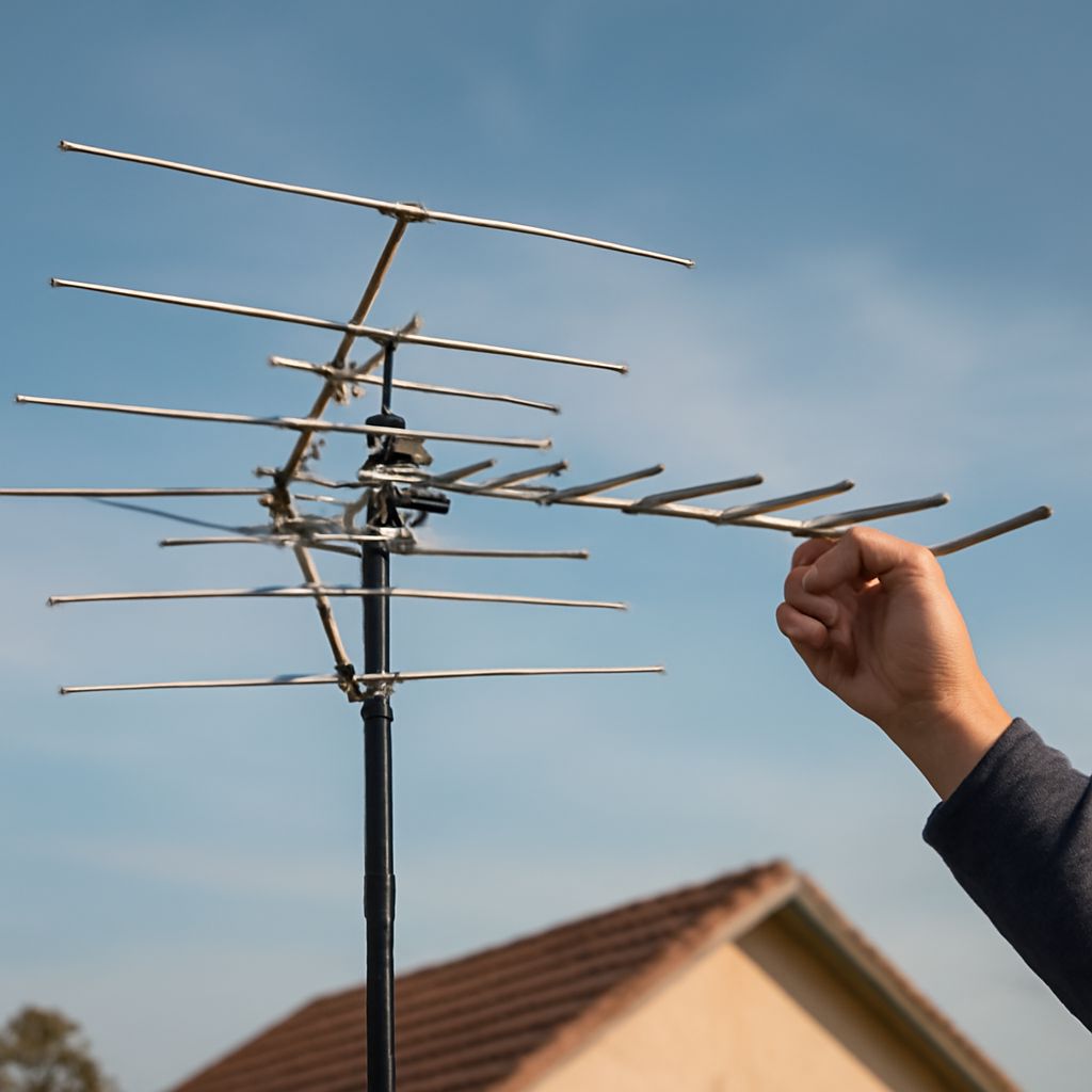
Choose a fixed TV antenna pole when the antenna serves stations in one direction and the installation has modest wind exposure. Choose a telescoping antenna mast when adjustment and service access matter more than maximum stiffness. Add a TV antenna rotor when reliable stations are separated by substantially different compass headings and one fixed aim cannot serve them.
The support must be sized for the complete assembly—not just the antenna. Include the mast height, antenna wind area, rotor weight, coax movement, mounting point, and local exposure. A tall mast that is stable with a small antenna may bend or loosen when carrying a large VHF array in open wind.
What must a TV antenna pole support?
A TV antenna pole supports vertical weight and resists bending, vibration, and twisting. The important load is often wind rather than dead weight. Wind pushes against the antenna’s projected area and creates leverage at the mast base. A large reflector, long VHF elements, or an attached rotor can increase that leverage considerably.
Match the support to these factors:
- Antenna area: A compact UHF panel usually presents less wind resistance than a long combination antenna with VHF elements and a large boom.
- Total weight: Add the antenna, rotor, mounting hardware, coax, and any preamplifier or accessory attached near the top.
- Unsupported length: The section above the highest bracket is the most flexible part. A longer exposed section needs a larger-diameter or heavier-wall mast, closer support points, or guy wires.
- Mounting surface: A roof tripod, eave bracket, chimney mount, or ground-supported mast transfers force differently. The structure—not only the metal tube—must carry the load.
- Wind exposure: A sheltered installation beside a building can tolerate a different arrangement from a rooftop, ridge, or open-field location.
Do not treat an advertised mast height as usable unsupported height for every antenna. Manufacturers commonly state a maximum length under particular load and wind assumptions. With a broad antenna, rotor, or exposed roof location, the practical unsupported height may be lower. A shorter, well-bracketed pole is generally more stable than a tall pole flexing above one bracket.
Keep coax routing in the support plan. Secure the cable below the antenna so its weight does not pull on the connector, but leave enough flexible loop for rotation if a rotor is installed. Avoid a tight cable bend or a loop that can catch on the mast, roof, chimney, or guy wires.
Is a telescoping antenna mast worth the easier adjustment?
A fixed pole is the simpler choice when the antenna will remain aimed at one transmitter group. It is usually stiffer for its height, has fewer moving parts, and needs less maintenance. A roof tripod or two-point eave mount can provide a solid installation when the antenna is not unusually large and the mast extension is kept moderate.
A telescoping antenna mast is useful when you need to raise, lower, or rotate the antenna during installation. Its sections can make it easier to test reception at several heights, replace a coax connector, inspect a preamplifier, or service a rotor without removing the entire support. It is especially convenient where a lift, tall ladder, or repeated roof access would be difficult.
That convenience has trade-offs:
- Stiffness: Telescoping sections become progressively smaller toward the top, so the upper section can flex more under a long antenna or strong wind.
- Height: The fully extended figure is not automatically a safe working height. Retract the mast or add guying when the antenna load and exposure require it.
- Adjustment: Clamps, locking pins, or sleeves must be fully engaged and checked after settling. A poorly locked section can slip and place the antenna or coax under sudden strain.
- Maintenance: More joints mean more points to inspect for looseness, corrosion, and water entry. Access is easier only if the mast can actually be lowered or reached safely.
Use the fixed option for maximum rigidity at a given moderate height. Use the telescoping option when testing height, periodic lowering, or service access has real value, then limit extension to the load and guying arrangement rather than the product’s headline length. If the antenna is large, a permanently supported mast with well-spaced brackets is often preferable to a fully extended lightweight telescoping design.
How does a UHF/VHF antenna change load and height needs?
A UHF/VHF antenna combines reception ranges that do not impose identical support demands. UHF elements can be compact, while VHF elements are physically longer and may produce a larger wind profile. A combination antenna can therefore require more mast stiffness even when its listed weight appears modest.
Height helps when terrain, nearby buildings, or trees block the signal path, but it is not a substitute for a sound installation or correct aiming. Raise the antenna enough to clear local obstructions and improve its radio horizon, then compare that benefit with the added bending force from a taller unsupported section. Extra height can worsen flexing, sway, and cable movement.
For a small antenna on a sheltered roof, two properly spaced brackets may be sufficient. A larger VHF/UHF array, a high roofline, or an open and windy site may call for a heavier mast, three or more support points, or guy wires. Guy wires should attach at an appropriate upper point, spread evenly around the mast, and terminate at sound anchors. They must be tensioned enough to control movement without pulling the mast out of alignment.
Also consider the rotor as part of the antenna load. A rotor adds weight at the top, increases the wind-catching assembly, and introduces a rotating joint. A heavy antenna on a light pole can overload the support even if the rotor itself turns correctly. A rotor-rated mast should be straight, rigid enough to avoid excessive oscillation, and secured against twisting at the mounting brackets.
When does a TV antenna rotor beat a fixed aim?
Test station directions before buying a rotor. List the desired stations, find their approximate compass bearings, and group them by direction. If the stations are clustered within roughly 20 to 30 degrees and the signals are usable, a fixed aim is usually the most reliable arrangement. A broad-pattern antenna may cover a wider cluster without moving parts, particularly when signals are strong.
If two groups are separated by about 40 to 60 degrees, test a broader antenna first if the site has adequate signal margin. Aim at the weaker group, then check whether the stronger group remains above the receiver’s reliable threshold. This option is simpler than a rotor, but it may reduce gain or allow more multipath interference from an off-axis station.
A TV antenna rotor is most useful when:
- Important stations lie in clearly different directions, such as one group to the northeast and another to the southwest.
- A narrow, higher-gain antenna is needed for weak or distant signals.
- Reception drops sharply when the antenna is aimed away from a transmitter.
- Viewers can accept a short turning delay when changing station groups.
Skip the rotor when stations are close together, the antenna receives them acceptably from one heading, or the installation cannot support the extra top weight and wind area. A rotor cannot overcome a blocked signal path, severe local interference, or an antenna that is too small for the weakest station.
For a rotor installation, allow a flexible coax loop below the rotating joint and secure the cable so it turns without snagging. Install the rotor according to its mast and antenna load limits, keep the mast plumb, and provide a service point for checking the controller, cable, clamps, and guy wires. If wind causes the mast to sway, solve the support problem before relying on precise rotor positioning.


