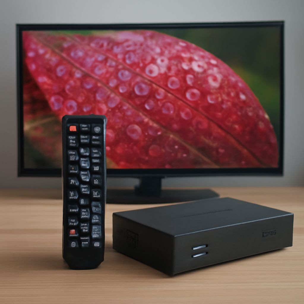
To receive low-VHF TV channels, start with the station’s physical RF channel—not its on-screen number. A compact UHF antenna can feed an ATSC tuner with HDMI perfectly and still miss a low-VHF signal if the antenna lacks elements long enough for that band. Identify the RF assignment, use an antenna that covers it, then scan that physical channel.
The tuner connects the antenna to the display, but it cannot compensate for an antenna with unsuitable band coverage, poor placement, or excessive signal loss in the coax path.
Which VHF TV channels use low VHF?
In North American over-the-air television, low VHF means physical RF channels 2 through 6, covering approximately 54–88 MHz. These are different from virtual channel numbers, which are the familiar numbers shown in the program guide.
For example, a station displayed as 2.1 might transmit on physical RF channel 35, which is UHF. Another station displayed as 5.1 might actually transmit on physical RF channel 5, which is low VHF. The decimal number identifies the station’s virtual program channel; the RF channel identifies the frequency your antenna must receive.
Check the station’s technical listing, reception database, or tuner’s signal details to find the physical channel. Do not choose an antenna based only on the virtual number. A station branded as channel 4 may not be using RF channel 4, while a station using RF 3 requires genuine low-VHF coverage.
Why does a low-VHF antenna need larger elements?
Lower frequencies have longer wavelengths, so an efficient antenna element must also be longer. As a useful comparison, a quarter-wave element is roughly 1.4 meters long around channel 2 and about 0.9 meter around channel 6. Antenna designs may fold, load, or combine these elements, but low-VHF reception still requires more physical length than UHF reception.
Look for specifications that explicitly list VHF-LO or channels 2–6. Marketing terms such as “digital,” “HD,” or even “VHF/UHF” do not prove that an antenna handles low VHF; some cover only high VHF channels 7–13. A suitable low-VHF antenna may be a larger outdoor model, especially at the edge of a station’s coverage area.
Place it as high and unobstructed as practical, ideally with a clear path toward the transmitter. For an indoor installation, test near an exterior wall or window and keep the antenna away from televisions, computers, LED lighting, and other noise sources. Low-VHF signals are particularly vulnerable to electrical interference.
How do you connect an ATSC tuner with HDMI?
- Connect the antenna’s coaxial cable to the tuner’s ANT IN, RF IN, or similarly labeled input.
- Connect an HDMI cable from the tuner’s HDMI OUT to an HDMI input on the television or monitor.
- Power on the tuner and display, then select the matching HDMI input on the display.
- In the tuner menu, choose Antenna or Air, not Cable, before scanning.
Use a sound RG6 coaxial cable with tight connectors. Avoid unnecessary splitters, long cable runs, and damaged wall plates. If a splitter is required, account for its loss before adding an amplifier. An amplifier cannot create a missing low-VHF signal and may overload the tuner when nearby stations are already strong.
How do you scan physical RF channels and fix a missing low-VHF station?
Run the tuner’s normal automatic scan first. It should find the station and attach its virtual number to the received RF signal. If the station is absent, use the tuner’s manual or targeted scan function:
- Find the station’s physical RF assignment and enter that number, such as RF 3, RF 5, or RF 6. Menus may call this “real channel” or “physical channel.”
- Watch the tuner’s signal-strength and signal-quality readings while the scan tests the channel. A lock or stable quality reading is more useful than strength alone.
- Compare the low-VHF reading with a known strong UHF station. High strength with poor quality suggests interference, multipath, or overload; low strength suggests inadequate antenna coverage, placement, or coax loss.
- Connect the antenna directly to the tuner, bypassing splitters and amplifiers, then repeat the targeted scan.
- Reposition or rotate the antenna, raise it if possible, and rescan RF 2–6. Keep the antenna’s low-VHF elements fully extended according to the manufacturer’s instructions.
If UHF stations work but every RF 2–6 station fails, verify that both the antenna and tuner support low VHF. Replace a UHF-only or high-VHF-only antenna with a model specified for VHF-LO. If the signal quality changes when lights, chargers, or appliances operate, remove that interference source or move the antenna and coax farther away.


