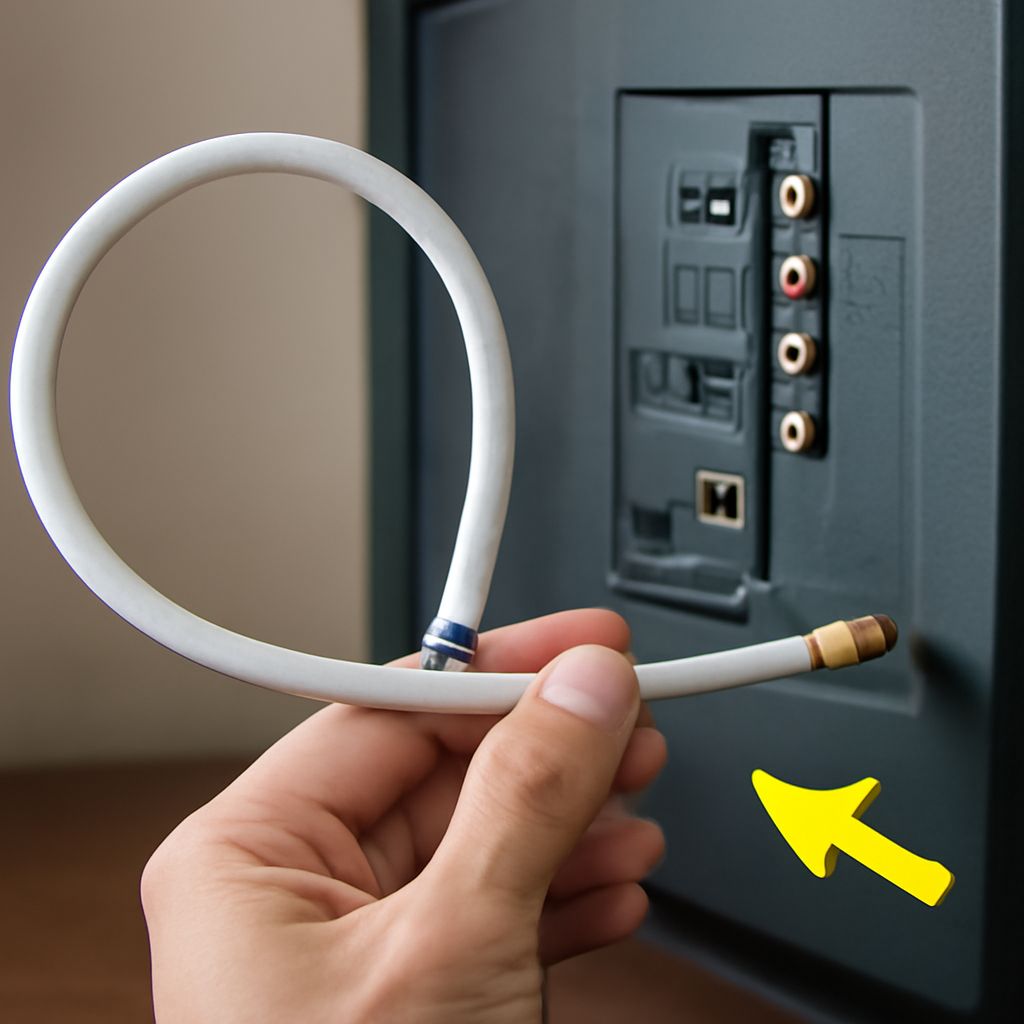
The best homemade TV antenna for most local UHF stations is a four-bay bowtie: four pairs of angled wire elements mounted on a nonconductive board, with a reflector behind them. It is inexpensive, directional, and similar in principle to many commercial antennas. If your market uses high-VHF channels, add a longer dipole or choose a design that includes VHF elements.
Build and test the antenna at an accessible height before putting any load on a chimney. That baseline lets you separate aiming problems from chimney condition, mast movement, and coaxial-cable loss.
Choose the best homemade TV antenna for local VHF/UHF channels
Check a local broadcast-channel listing and note whether the stations use low VHF, high VHF, or UHF. A compact bowtie is mainly a UHF design. For channels 14–36, start with four bowtie bays; each wing can be about one-quarter wavelength at the center frequency, roughly 4.5–6 inches for 470–608 MHz. Leave a 1–2-inch gap at each bowtie’s center and space adjacent bays about 8–10 inches apart.
High-VHF channels 7–13 need longer elements. A half-wave dipole is a useful starting point: its total length in inches is approximately 5,616 divided by the center frequency in MHz. That produces roughly 26–32 inches across the 174–216 MHz range. Low-VHF channels require substantially longer elements, so a small UHF bowtie may perform poorly even when nearby UHF stations are strong.
A rear reflector, made from parallel wire or metal rods, can improve forward reception. Keep it a few inches behind the driven elements without allowing it to touch them. Commercially styled antennas generally add a rigid reflector, weatherproof feed-point housing, and more precise element spacing; copying those features improves consistency, but accurate aiming and a sound coax connection still matter more than appearance.
How to make a TV antenna: build the elements, add a balun, and connect coax
- Cut a straight wood, PVC, or fiberglass support long enough for four UHF bays. Avoid metal near the active elements.
- Make eight identical wire or aluminum wings. Bend each pair into a shallow V, preserve the center gap, and fasten the pairs in parallel rows. Keep every bay symmetrical.
- Install a reflector behind the bays if the antenna will face a single transmitter direction. Maintain the same spacing across the entire antenna.
- Connect one side of every driven element to one terminal and the opposite side to the other terminal. Do not let screws, wire ends, or the reflector bridge the two sides.
- Attach a 300-ohm-to-75-ohm balun to those terminals, then connect the balun to RG-6 coax. Seal the outdoor connection with weatherproof tape or a coax seal.
Use a strain-relief loop or tie point so the coax connector carries no mechanical weight. Keep the cable away from sharp edges and avoid tight bends. A loose connection, crossed element, or damaged balun can reduce reception more than a small aiming error.
Test the antenna before roof mounting and record a channel-scan baseline
Place the antenna in a yard, attic, or upper-room location where you can safely rotate and reach it. Connect the same television and coax you plan to use later. Select the television’s antenna or over-the-air input, run a complete channel scan, and record every received channel along with its signal-quality reading when available.
Rotate the antenna in small steps, such as 10–15 degrees, allowing the TV’s signal meter time to respond. Record the best direction and note channels that break up, disappear, or remain stable. A successful baseline includes several repeatable scans, not one lucky result. If only UHF stations appear, check the local frequency list before rebuilding; the missing stations may require longer VHF elements.
Plan a TV antenna chimney mount, route coax, and compare reception after aiming
Inspect the chimney before choosing a TV antenna chimney mount. Do not use a chimney with loose bricks, cracked mortar, leaning masonry, damaged caps, or other signs that it cannot resist antenna wind load. Mounting bands or brackets should sit on sound masonry without crushing it. Use two bands or bracket points, typically separated vertically by about 18–36 inches, so the mast does not twist. Follow the mount’s load rating and keep the mast extension as short as practical; a tall mast increases leverage and wind force.
Keep the antenna clear of the flue outlet, hot exhaust, roof edges, and nearby metal that could obstruct its forward pattern. Route coax down the mast with UV-resistant ties, leaving a small drip loop below the feed point. Do not let the cable hang from the balun. Use a grounded entry point or coax grounding block where appropriate, and seal every outdoor connector while preserving a gentle bend radius.
After securing the mount, aim the antenna toward the transmitter direction found during the baseline test and run another complete channel scan. Compare the before-and-after channel lists, signal readings, and picture stability using the same television and cable. If reception worsens, first check mast movement, connector strain, water intrusion, and excessive coax length; then rotate the antenna in small increments and rescan.


