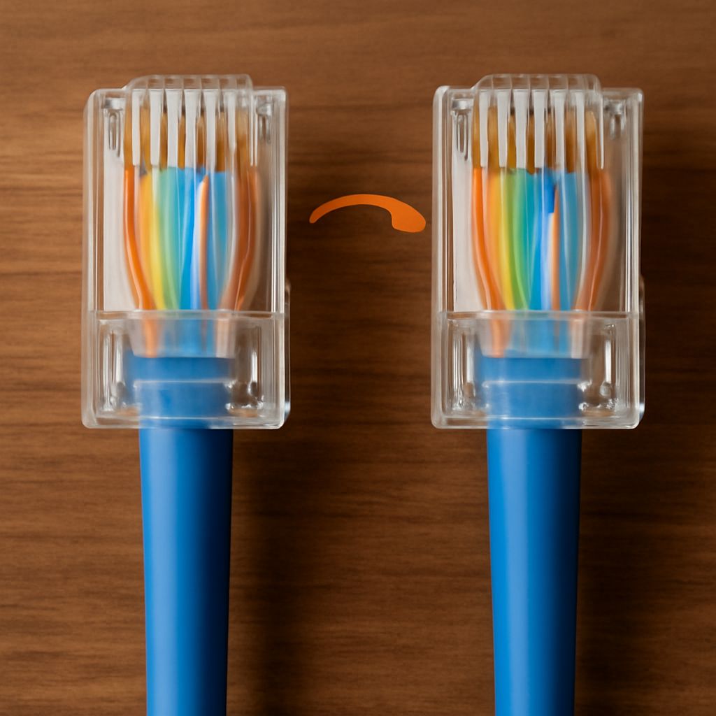
Use the same color order at both ends for an ordinary straight-through Ethernet cable: T568A at both ends or T568B at both ends. The wiring diagram for an Ethernet cable below shows all eight contacts. Hold each plug in the same orientation before comparing colors, and keep each twisted pair together as close to the contacts as the connector permits.
Ethernet Cable Wiring Diagram: Read the Pins
Hold a male 8P8C plug with the cable entering from the bottom, the gold contacts facing you, and the retaining latch pointing away from you. In that view, pin 1 is on the left and pin 8 on the right. The table follows Leviton’s pin assignments; its installation guide also describes viewing a plug from the cable-entry side with the clip down.
| Pin | T568A | T568B |
|---|---|---|
| 1 | White/green | White/orange |
| 2 | Green | Orange |
| 3 | White/orange | White/green |
| 4 | Blue | Blue |
| 5 | White/blue | White/blue |
| 6 | Orange | Green |
| 7 | White/brown | White/brown |
| 8 | Brown | Brown |
White/green means the mostly white conductor marked with green. In each Ethernet wiring diagram, pins 4 and 5 carry the blue pair; pins 3 and 6 carry another pair even though they are separated by the blue wires in the plug. T568A and T568B exchange the green and orange pairs. The table is a wiring chart for Ethernet cable: each contact has a designated wire.
Straight-through or crossover?
For a straight-through patch cable, match the same scheme at both ends: A-to-A or B-to-B. Pin 1 connects to pin 1, pin 2 to pin 2, and so on. Follow an existing installation’s scheme for easier repairs.
A crossover with A on one end and B on the other exchanges pairs 1–2 and 3–6. Modern Ethernet devices often support automatic crossover detection, so a straight-through cable is generally the practical choice. Use a crossover when the equipment instructions call for it.
Match the parts before crimping
Choose a copper twisted-pair cable and an 8P8C plug intended for its category, conductor type, conductor gauge, and outside diameter. Solid conductors are common in permanent in-wall cable; flexible patch cable usually uses stranded conductors. A plug made for one may not grip or contact the other correctly. Some accept both: IDEAL’s Cat 6 plug specifications give one such example.
Use a compatible crimper, cable stripper, and cutter. Feed-through plugs require a compatible tool that trims the protruding wires; closed-end plugs are cut to length before insertion. Some designs also use a load bar or guide. Follow the plug manufacturer’s sequence for that part, because a color chart for Ethernet cable cannot describe every connector.
Prepare and terminate each end
To learn how to wire an Ethernet cable, start with the cable disconnected from equipment. Slide any boots onto the cable before attaching the plugs. Work one end at a time:
- Strip the jacket. Remove the length specified by the plug maker without nicking the insulation on the eight conductors. If a conductor is damaged, cut back and start again.
- Arrange the wires. Separate the four pairs and untwist only enough to put the conductors in the chosen order. Keep the remaining twists close to the plug. Flatten the wires side by side and compare them with the Ethernet cable wiring diagram above.
- Insert the conductors. For a closed-end plug, trim the ends evenly to the length required by its instructions and push each wire into its own channel until it reaches the front. For a feed-through type, pass the wires through the nose as directed. Push the jacket under the strain-relief tab so it grips the jacket.
- Inspect and crimp. With the latch away, check the color order and that every wire is fully seated. Put the plug in the matching crimper and complete the tool’s full stroke. Check that the jacket is held and that the conductors have not shifted. Repeat at the other end with the same scheme for a straight-through cable.
Wiring an Ethernet cable requires matching the plug and tool instructions to the parts. Leviton’s feed-through instructions, for example, specify insertion and trimming for that connector; a closed-end design has a different preparation step. Keep an Ethernet cable pinout diagram beside the work until both ends are terminated.
Test the cable, then diagnose
A basic continuity or wire-map tester sends a signal through each conductor and shows opens, shorts, and incorrect pin connections. Connect the main unit to one end and its remote to the other, run the test, and compare the result with the selected straight-through or crossover pattern. The Ethernet plug wiring must match the intended pin map at both ends. A diagram of Ethernet cable wiring helps verify the wiring of the Ethernet plug.
A simple continuity test may miss a split pair: both ends can connect pin to matching pin while conductors from different twisted pairs occupy positions intended for one pair. The cable may pass continuity yet suffer interference. Fluke Networks explains this fault. Use a tester that specifically detects split pairs; a qualification or certification instrument is needed when the goal is to assess performance rather than pin continuity alone.
When wiring an Ethernet cable, a reversed view or misplaced conductor is often visible through the plug. Compare both ends with the same Ethernet wiring diagram, contacts facing you and latch away. If a tester reports a split pair, inspect the paired colors as well as the pin numbers; cut off the faulty plug, restore the correct pair order, and terminate it again with a new connector.