A receiver may list a frequency range while a signal is described by its bandwidth. Will the two fit? Start by finding the frequencies at each edge under the same measurement rule, then compare the span and its position. That turns a bandwidth and frequency specification into a practical decision.
Bandwidth frequency edges: define what counts
A signal or device has a frequency bandwidth equal to the distance between two selected frequencies. The lower edge is fL and the upper edge is fH. Both must use the same unit: hertz (Hz), kilohertz (kHz), megahertz (MHz), or gigahertz (GHz). One MHz equals one million Hz.
The edges depend on the question. A filter’s frequency range might be defined by the points where its output power falls to half its reference value, approximately −3 dB. For a signal, an occupied-bandwidth specification may instead contain a stated percentage of transmitted power. These criteria can give different boundaries for the same spectrum. Record the rule with the numbers so another person can reproduce the comparison.
The bandwidth frequency range also has a position on the spectrum. A 10 MHz span around 100 MHz and a 10 MHz span around 900 MHz have the same width, but a receiver designed for one range may not tune to the other.
Calculate width and center
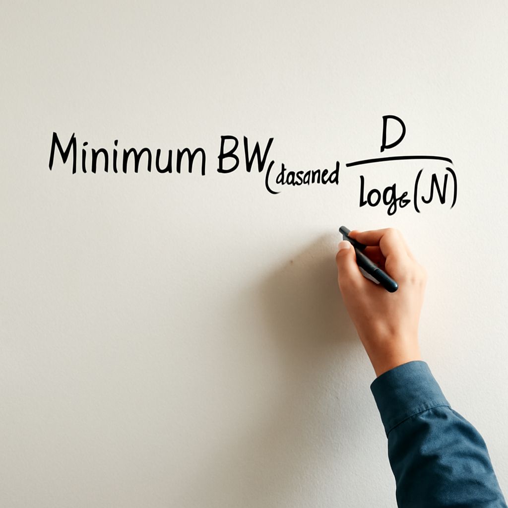
Once the edges are defined, the formula for bandwidth is:
Bandwidth = fH − fL
For a simple arithmetic midpoint, center frequency = (fH + fL) / 2. Some filter specifications use a geometric center instead, so use the definition supplied for the device when comparing published values.
Suppose a filter’s response reaches its stated −3 dB points at 90 MHz and 110 MHz. This is an illustrative example, with both points measured relative to the same reference response:
- Width: 110 − 90 = 20 MHz.
- Arithmetic center: (110 + 90) / 2 = 100 MHz.
- In hertz, the width is 20,000,000 Hz.
This bandwidth formula gives 20 MHz, centered at 100 MHz. A signal with significant components from 95 to 105 MHz fits within those edges, but its actual distortion still depends on the filter response across that interval. A −3 dB edge is already below the reference level; a passband needing flatter response should leave room inside it.
The formula for calculating bandwidth also works when the span starts at zero. If a low-pass circuit passes frequencies from DC, or 0 Hz, to a stated 3 MHz cutoff, its width under that cutoff criterion is 3 MHz. Subtract only the specified edges.
Choose a range for the job
Use the bandwidth calculation formula on the frequencies the signal must carry, then compare the result with the system response and tolerated loss.
- Define the signal edges. Use the required power containment or amplitude threshold. For a modulated radio signal, include its sidebands under that chosen rule.
- Check the device edges. A tuner, antenna, filter, and amplifier can each constrain the usable range. Compare their frequency bands for bandwidth and location using compatible criteria.
- Leave practical margin. If the signal reaches a filter’s cutoff, its outer components will be attenuated. Check the response curve across the actual signal range and allow for the stated tuning tolerances.
- Consider interference. A wider receiver admits more unwanted energy. Allow for signal and tuning tolerances while rejecting nearby signals.
In audio, a 20 Hz–20 kHz response describes an input-frequency range only when its tolerance is stated; a speaker may vary considerably within it. In RF, a channel allocation, an emitted signal’s occupied span, and a receiver’s passband are different specifications. Compare their frequency limits and bandwidth using their definitions.
Optical systems also describe a span, sometimes in wavelength units such as nanometers. Frequency and wavelength are inversely related, so convert both wavelength edges to frequencies before subtracting if the answer is needed in Hz. Do not treat a nanometer width as a fixed number of hertz at every wavelength.
Bandwidth, data rate, and fast edges
A connection’s data rate is measured in bits per second; a bandwidth measured in Hz describes a frequency span. More spectrum can support more data under suitable conditions, but modulation, coding, noise, and signal power also affect the result. A 20 MHz channel does not automatically carry 20 million bits per second.
Sampling introduces another relationship. For an ideal, band-limited baseband signal with highest frequency B, the Nyquist sampling theorem calls for a sampling rate greater than 2B for reconstruction under its assumptions. The highest frequency is measured from zero here; a bandpass signal needs its own sampling analysis. The theorem does not turn frequency bandwidth into a universal bit rate.
For a measurement system with an approximately Gaussian response, the 10%–90% rise time and its −3 dB bandwidth are related approximately by rise time = 0.35 / bandwidth. With bandwidth in Hz, the result is in seconds. A different response shape or rise-time definition changes the constant; Tektronix explains the assumptions. For example, 100 MHz gives an estimated 3.5 nanoseconds for that instrument response. Choose a faster instrument than the edge being measured to reduce measurement error.
What if only the center and width are given?
For symmetric edges, reverse the bandwidth formula: divide the width by two and subtract and add it to the arithmetic center. A 100 MHz center and 20 MHz width give 90 MHz and 110 MHz. If the specification uses a different center convention, use that convention to recover the edges.