The right antenna depends on the frequencies you need and what you want to do with them. A television viewer may need reliable reception from several stations; a radio operator may also transmit, while a lab may measure field strength. Log-periodic antennas can serve these different jobs, but an LPDA’s usable frequencies must match the job.
A log-periodic dipole array, or LPDA, uses a series of dipoles arranged along a boom. Each dipole is a conductor split into two arms. Their lengths and spacing change in a regular progression, giving the array its distinctive tapered shape. The design is one member of the broader log-periodic family: a wideband antenna is not automatically an LPDA.
LPDA antenna: How the array works
Imagine sending a signal into an array of different-sized dipoles. At a given frequency, the elements around the appropriate electrical length carry much of the current and contribute strongly to radiation. This is the active region. As frequency rises, that region shifts toward the shorter elements; as frequency falls, it shifts toward the longer ones. Several nearby elements participate, so the boundary is not a sharp line.
The elements of this periodic antenna array are connected to a feed structure that alternates their electrical connection. Their currents combine to produce a directional beam, generally toward the shorter-element end. On reception, the same structure gathers energy most effectively from that direction. The pattern has width, however, and can also have sidelobes and a rear response. A nearby wall, mast, or reflecting building can change what arrives at the receiver.
The LPDA’s feed and recurring geometry allow a log periodic antenna to work across a substantial range rather than at just one narrow resonance. The dimensions and number of elements in this logarithmically periodic array set practical limits. Below the intended range the longest elements may be too short for effective operation; above it the shortest elements and feed details become limiting. The specified range is therefore more informative than the tapered outline alone.
What broadband performance means
A second log periodic antenna can cover the same band as the first yet produce a different result at a particular frequency. Broadband operation means that the design meets its stated operating conditions across a range. It does not mean that gain, impedance, beamwidth, or front-to-back ratio stay perfectly constant. Ask for curves or values across the band, especially at the frequencies that matter most.
Gain describes how strongly the antenna concentrates power in a given direction compared with a reference antenna. A higher figure can help when a wanted signal is weak, provided the beam points at it. A narrower beam may make signals arriving from widely separated directions harder to receive without turning the array. For TV, compare station directions and actual broadcast frequencies before choosing the mounting position.
Input impedance describes the electrical load presented at the feed. A mismatch with the cable can reflect some power back along the line; manufacturers often express that match as VSWR or return loss. Check the value over the working band, not just the nominal impedance printed on the connector. Cable loss also rises with length and often with frequency, so a long run can consume part of the benefit of directional gain.
Reception, transmission, and measurement
For reception, aim the log-periodic antenna toward the source and match its polarization: horizontal elements for a horizontally polarized signal, for example. Use a suitable cable and weatherproof outdoor connections. If several sources are in different directions, compare the beam pattern with their bearings before relying on one fixed mounting angle. An amplifier can compensate for some downstream cable loss, but cannot recover a signal already buried in noise at its input.
For transmission, the LPDA antenna must cover the transmit frequency and tolerate the transmitter’s power and operating duty cycle. Check the manufacturer’s continuous and peak ratings as applicable, along with the match at the operating frequency. Excess reflected power can stress a transmitter; follow its specified limits and use a compatible feed line. Keep the installation clear of power lines and follow applicable exposure and mounting requirements.
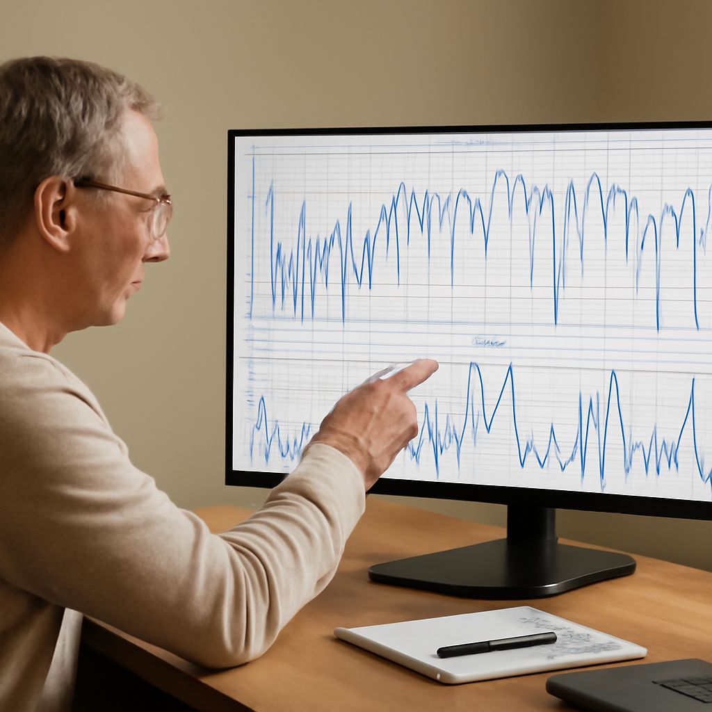
For measurements, an LPDA’s calibration matters as much as its coverage. A spectrum analyzer reads the signal at its input, not field strength directly. A calibrated antenna factor, cable loss, and the measurement setup convert that reading into a field-strength estimate. The manufacturer’s HL033 specifications illustrate a model intended for both transmission and measurement; its figures apply to that model, not every array.
Make the choice fit the job
Start with the lowest and highest frequencies, then compare the directional pattern and gain at the specific channels or test points. For an LPDA design used for transmission, add power handling and match; for a measurement setup, add calibration and cable corrections. An LPDA array intended for indoor testing may need different mechanical protection from one mounted outdoors, and connector type must suit the cable.
Choose a log-periodic array only when its published performance at the frequencies, directions, and power levels you actually need supports the job.