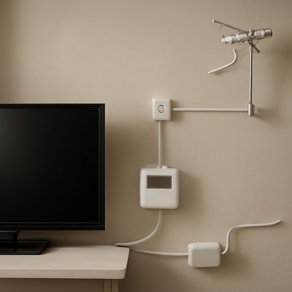
Digital TV frequencies identify the physical radio-frequency channel carrying a broadcast; they are not necessarily the same as the channel number shown on the screen. The transmission combines compressed program streams, service data, error protection, and modulation into one RF signal that an antenna can receive.
So, how does digital TV work? A broadcaster creates a digital stream, a digital TV transmitter converts it into a modulated radio signal, and the antenna and tuner reverse that process so the television can display the selected program.
How Does Digital TV Work From Transmitter to Receiver?
The path has five practical stages:
- Program production: Video and audio are encoded and compressed into separate data streams.
- Multiplexing: A multiplexer combines several programs, electronic program data, and service information into one transport stream.
- Modulation: The transmitter applies error correction and maps the data onto radio-frequency symbols. Depending on the broadcast standard, this may use 8VSB or an OFDM-based method.
- RF transmission: The signal is upconverted to the assigned physical RF channel and amplified. The transmitting antenna radiates it over the coverage area.
- Reception: A receiving antenna captures the RF energy. The TV tuner selects the channel, demodulates the signal, corrects errors, separates the program streams, and decodes the chosen audio and video.
Digital television does not send each program on a separate visible channel in the same way an older analog system did. Several services can share one RF channel because compression and multiplexing allow the broadcaster to package them together. The receiver uses the station’s service data to identify the programs and present them in the channel guide.
How a Digital TV Transmitter Carries Programs
The transmitter begins with an encoded transport stream rather than a finished picture moving directly through the air. Video is compressed to reduce its data rate, while audio and program metadata are packaged alongside it. The multiplexer assigns identifiers to each stream so the receiver knows which audio belongs to which video and which services are available.
Before transmission, the system adds forward-error-correction data and interleaves parts of the signal. These techniques help the receiver recover information affected by noise or brief interference. The modulator then converts groups of digital bits into symbols and places those symbols within the broadcaster’s allocated RF bandwidth.
The output is a continuous radio signal centered within a physical channel. In North American over-the-air broadcasting, a standard terrestrial RF channel generally occupies 6 MHz, although channel bandwidth depends on the country and transmission standard. The transmitter’s power, antenna height, terrain, buildings, and interference all affect how much usable signal reaches a receiving antenna.
Virtual Channels Versus Digital TV Frequencies
A television may display a station as 5.1, while the broadcast actually arrives on physical RF channel 33. The first number is a virtual or major channel number, and the number after the decimal identifies a program service. Neither number, by itself, tells you the radio frequency carrying the transmission.
The physical RF channel corresponds to a defined frequency range and is what the tuner must receive. A station can keep its familiar virtual channel while changing its RF assignment, and multiple virtual services can share one physical RF channel. This is why aiming an antenna using only the displayed channel number can produce an incorrect result.
To identify the actual frequency, check the television’s tuning or diagnostic screen, a broadcast-station technical listing, or an antenna-meter channel database. Look for labels such as RF channel, physical channel, frequency in MHz, or center frequency. Use that physical value when configuring a meter or comparing reception between locations.
What a Digital TV Signal Meter Measures During Troubleshooting
A digital TV signal meter normally reports more than one measurement. The labels and scales vary by device, so percentages are useful mainly for comparing readings made with the same meter.
- Signal level: This estimates received RF power, commonly shown in dBm, dBµV, or a relative percentage. A low level can result from distance, obstructions, antenna limitations, cable loss, splitters, or loose connections.
- Signal quality: This indicates how cleanly the receiver can interpret the symbols. It may be derived from SNR, MER, or another quality calculation.
- BER: The bit-error rate shows how much data is being received incorrectly. A lower BER generally indicates a more reliable signal.
- Lock: A lock confirms that the meter has synchronized with the selected modulation and decoded enough data to identify the transmission.
For antenna adjustment, select the station’s physical RF channel, not its virtual number. Rotate or reposition the antenna slowly, pause for the meter to average each reading, and record both level and quality. Aim for the highest stable quality or MER and the lowest BER while keeping sufficient level. Then check the other desired RF channels, because the best position for one transmitter may not be perfect for another.
A stronger level is not always a better signal. If level increases while quality falls, the antenna may be receiving multipath reflections, interference, or an excessively strong signal that overloads a preamplifier or tuner. If level and quality both remain low, inspect the antenna direction, coaxial cable, connectors, splitters, and obstructions. Digital reception can change abruptly: a small loss in quality may turn a watchable picture into freezes or complete breakup.


