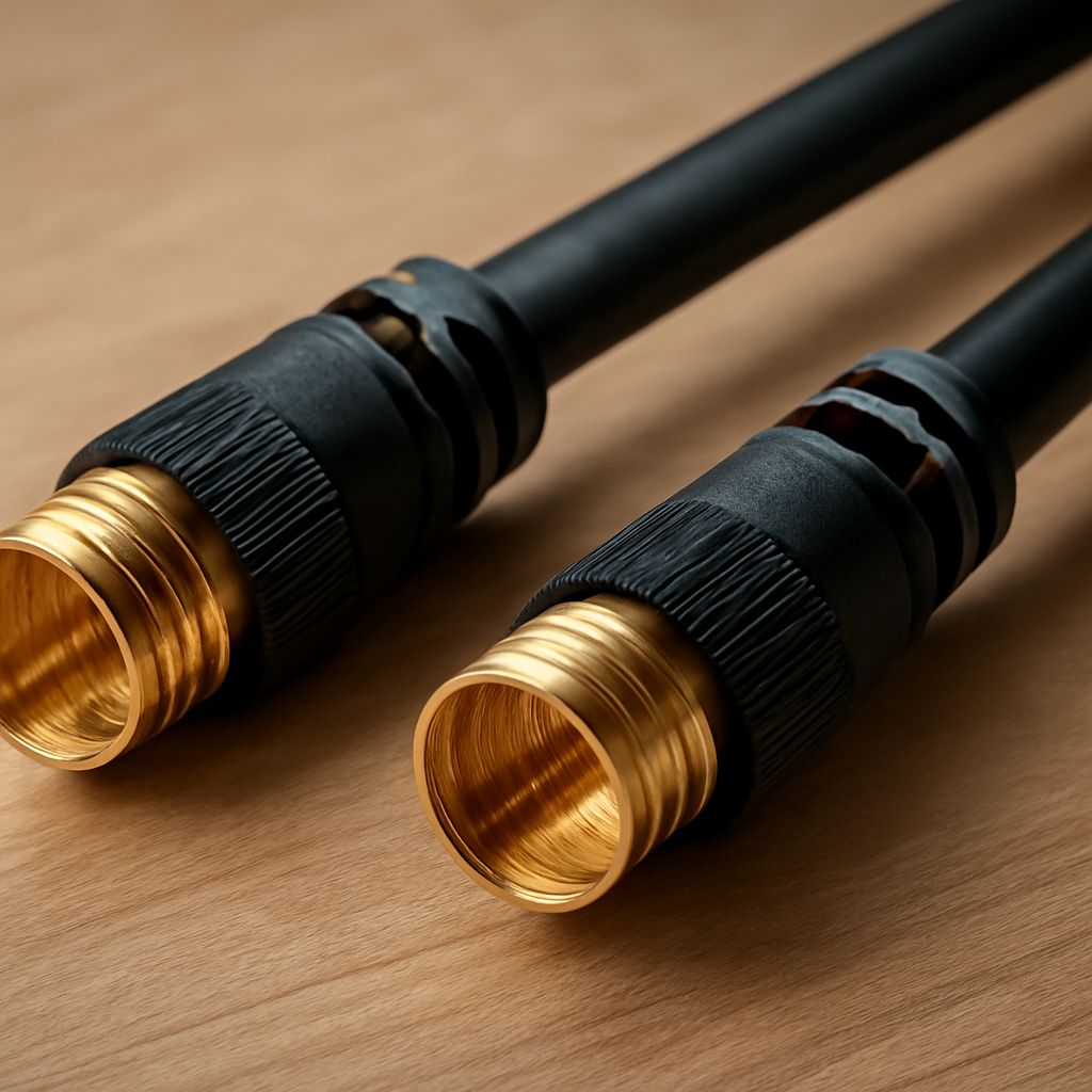
An ATSC DVR receives free over-the-air broadcasts through an antenna connected to its RF antenna input. Use one 75-ohm coaxial path from an antenna that covers both VHF and UHF, select the DVR’s antenna or terrestrial mode, and run a channel scan. Choose the antenna by each station’s physical RF channel, not by the channel number shown on screen.
After the scan, confirm that every expected station appears and make a short test recording. If the DVR receives one band but not the other, check the antenna’s coverage, aiming, connectors, splitters, and amplifier before replacing the coax.
What does an ATSC DVR receive over one antenna?
How virtual channel numbers differ from physical RF channels
A station’s displayed number is usually a virtual channel, such as 5.1 or 12.1. Its broadcast may actually travel on a different physical RF channel. For example, a station displayed as 5.1 could transmit on physical RF channel 27, which is UHF.
Look up the physical RF channel for each local station in a reliable station database or reception map. Use that RF number to determine the required antenna band. Do not assume that a low virtual number means the station uses VHF.
What the DVR tuner input actually receives
Connect the antenna coax to the DVR port labeled ANT IN, RF IN, or ANTENNA. The tuner receives the antenna’s radio-frequency signal, decodes the digital broadcast, and maps it to the station’s virtual channel. Connect the DVR’s HDMI output separately to the television.
In the setup menu, choose Antenna, Air, or Terrestrial rather than Cable. A cable-TV scan can use different channel plans and may fail to find broadcast stations.
How do you identify each station’s VHF band?
Use station listings to find the physical RF channel
List every desired station and record its physical RF channel. In North American ATSC broadcasts, RF channels 2 through 13 occupy the VHF band. Channels 14 and above are generally UHF, although local allocations can change as stations move or repack frequencies.
Separate VHF into low VHF, channels 2 through 6, and high VHF, channels 7 through 13. An antenna advertised only for high VHF and UHF may not perform well on a low-VHF station. Verify the full coverage range rather than relying only on the words “digital antenna.”
Confirm whether local stations also use UHF
Most markets use a mix of bands. A station with a familiar virtual number may be physically UHF, while another may use high VHF. Mark each station as low VHF, high VHF, or UHF, then choose an antenna that covers all three groups required at your location.
How do you choose an antenna for both VHF and UHF?
Match antenna coverage to the stations’ physical RF channels
Choose an antenna specifically rated for the physical channels on your list. If you need channels in both VHF and UHF, use a combination VHF/UHF antenna rather than a UHF-only indoor model. For low-VHF reception, a larger antenna with suitable elements may be necessary.
Consider antenna placement, aiming, and amplification
Place the antenna as high and unobstructed as practical, aim it toward the transmission towers, and rescan after changing its position. Outdoor or attic placement often provides a more stable signal than placement behind dense walls or metal objects.
An amplifier can compensate for a long cable run or splitter loss, but it cannot add a missing frequency band. Excessive amplification can also overload the tuner. If the signal is already strong, test the antenna without the amplifier before adding gain.
Why is VHF cable not a separate coax path?
How 75-ohm coax carries both broadcast bands
There is normally no need for separate VHF cable and UHF cable when connecting an antenna to an ATSC DVR. Standard 75-ohm coaxial cable, such as RG6, carries the broadcast frequencies used by both bands through the same conductor and shielding. The antenna selects or receives the frequencies; the coax transports them together.
Use coax with F-type connectors that match the antenna and DVR. RG6 is a practical choice for longer indoor or outdoor runs. Keep the cable continuous where possible, avoid sharp bends, and use weatherproof connections outdoors. A cable labeled for satellite or broadband use can also work if it is 75 ohms and properly terminated.
Where connectors and splitters add signal loss
Every connector, wall plate, join, and splitter introduces some loss. A two-way splitter commonly reduces each output by roughly 3.5 to 4 dB, with additional loss from the cable itself. Remove unused splitters for testing, or connect the antenna directly to the DVR to establish a baseline.
What does UHF cable mean in this setup?
The phrase UHF cable may describe coax marketed as suitable for UHF frequencies, not a special cable required only for UHF. Do not confuse it with a UHF connector, which is a separate connector type and is not the usual antenna-to-DVR connector. For this setup, the normal choice remains 75-ohm coax with F connectors.
How do you scan and troubleshoot missing channels?
How to connect the tuner, scan channels, and schedule recordings
- Connect the antenna directly to the DVR’s antenna input.
- Select the antenna, air, or terrestrial tuning mode.
- Start an automatic channel scan and let it finish completely.
- Check the results against your physical RF channel list and confirm that each virtual channel displays correctly.
- Watch several minutes of a station, then schedule a short recording and play it back.
Once reception is reliable, reconnect any required splitter or distribution amplifier and scan again if the DVR loses channels. Keep the recorder’s clock, guide data, and recording storage configured so scheduled programs can start and finish correctly.
What to check when one band is missing
If UHF stations work but VHF stations do not, the antenna may be UHF-only, may not support low VHF, or may be poorly aimed for the VHF transmitters. If VHF works but UHF is missing, check the antenna’s UHF rating, aiming, and nearby interference. In either case, inspect F connectors for loose center conductors, damaged braid, corrosion, or a short between the shield and center pin.
Test with one uninterrupted coax run directly to the DVR. If both bands work there, the removed splitter, wall plate, amplifier, or cable section is causing the loss. If one band is still absent, move or replace the antenna with a model covering the missing physical RF channels, then run a fresh scan.


