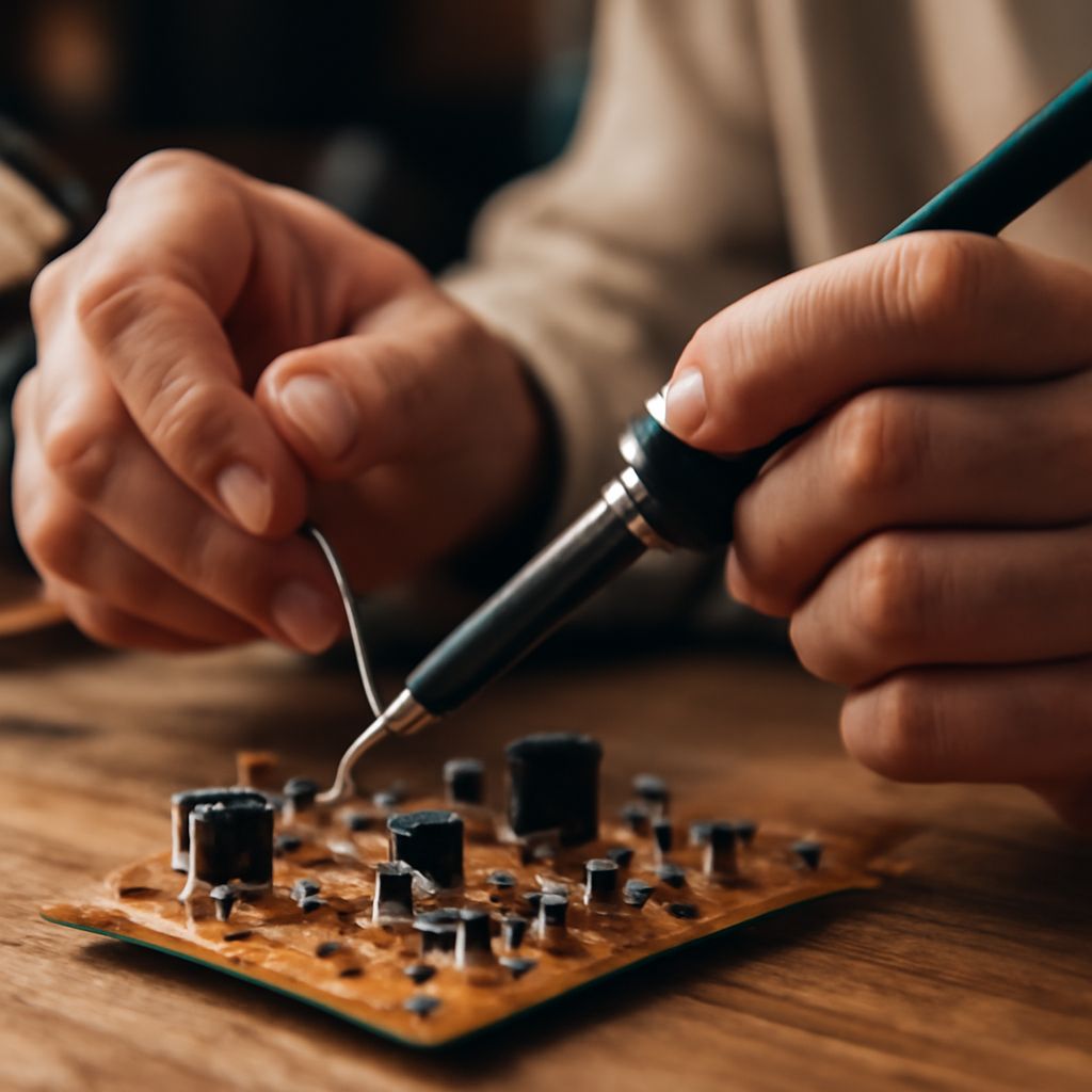
Build and test the antenna while the mast is still low, then raise the tower only after the antenna, coax, and aiming are proven. A crank up antenna tower makes servicing easier, but its moving sections add cable movement, wind loading, and locking requirements that can create faults if they are ignored.
Use a short temporary coax run for the first test. Compare that result with the complete tower-to-TV run before deciding whether amplification is necessary.
Build and test the DIY digital TV antenna at low height
Start with the local broadcast channel list and separate the required VHF and UHF channels. A compact bow-tie or whisker design works well for UHF, while VHF requires substantially longer elements. If your market uses both bands, build a combination antenna with a larger VHF element set and a UHF bow-tie array, or use separate elements joined through an appropriate combiner.
- Cut the elements to the design dimensions for the target channel range. Keep the driven elements symmetrical and mount them on a rigid, nonconductive boom.
- Add a reflector or screen behind a directional element set if the transmitter direction is known. Connect the feed point to a 300-to-75-ohm balun, then attach outdoor-rated 75-ohm coax.
- Place the antenna on a temporary mast at the intended service height. Keep it away from metal siding, roof edges, and nearby wiring.
- Point it toward the transmitters and run a tuner channel scan. Record signal strength and, more importantly, signal quality or error readings for weak channels.
Rotate the antenna a few degrees at a time and rescan or use the TV’s manual signal screen. A channel that breaks up with a strong-looking signal usually indicates multipath, interference, or an antenna problem—not a need for more gain. Repair loose connections and retest before moving on.
Plan the crank-up antenna tower and its service position
Choose a low service position where you can reach the antenna, balun, coax connector, winch, and locking hardware without climbing. Mark the tower’s fully lowered position and confirm that the antenna clears the roof, fences, and vehicles while it is raised.
A crank-up tower normally uses telescoping sections, a hinge or pivot, a winch, and locking pins or bolts. Inspect every section, verify that locks engage fully, and use the manufacturer’s specified guy points. Guys must be tensioned evenly and attached to anchors that can resist the tower’s wind load. The antenna, mast, rotor, and coax all add surface area, so do not exceed the tower’s rated height or projected load.
With the tower lowered, fasten the antenna and make the short-cable test again. Then raise it slowly while watching for snags, leaning sections, loose guys, or cable pinch points. Stop at each locking position and secure the tower before connecting or servicing equipment.
Route coax through the moving tower and compare reception paths
Use one continuous outdoor-rated coax run where practical. Secure it to fixed points with loose UV-resistant clips, but leave a controlled loop at the hinge or transition where the cable must move. The loop should flex as the tower rises and lowers without rubbing on a section, entering the winch, or becoming trapped between joints. Add strain relief at the antenna and a downward drip loop before the cable enters a building.
Make two controlled measurements:
- Direct path: connect the antenna to the TV with the shortest practical cable while the tower is in its low service position.
- Distributed path: use the permanent cable, connectors, grounding block, wall entry, splitters, and any existing distribution hardware.
Keep the antenna direction and TV tuner unchanged. Test the same weak channels on both paths and record dropouts, quality, and strength. A large direct-to-distributed difference points to cable length, connectors, splitters, or damage. Check those items before adding gain.
Add a DIY TV antenna booster only for measured feed-line loss
Estimate loss from the cable manufacturer’s dB-per-length specification and add the loss of connectors and splitters. Then verify it with the two path tests. A long cable run and several splits may justify amplification; a short run normally does not.
Use a low-noise preamp at the antenna, before the long coax run, when the measured loss occurs between the antenna and the first tuner or splitter. Select enough gain to overcome that loss without overloading strong local stations. Use a distribution amplifier indoors, after the incoming cable and usually near the splitter, when one adequate signal must feed several televisions.
Power the preamp through its approved injector and confirm that the power pass reaches the masthead unit. After installation, rescan and compare the previously weak channels. If quality does not improve, remove the booster and return to antenna aim, element dimensions, cable condition, and tower alignment; amplification cannot correct a mistuned antenna, damaged coax, or poor aim.


