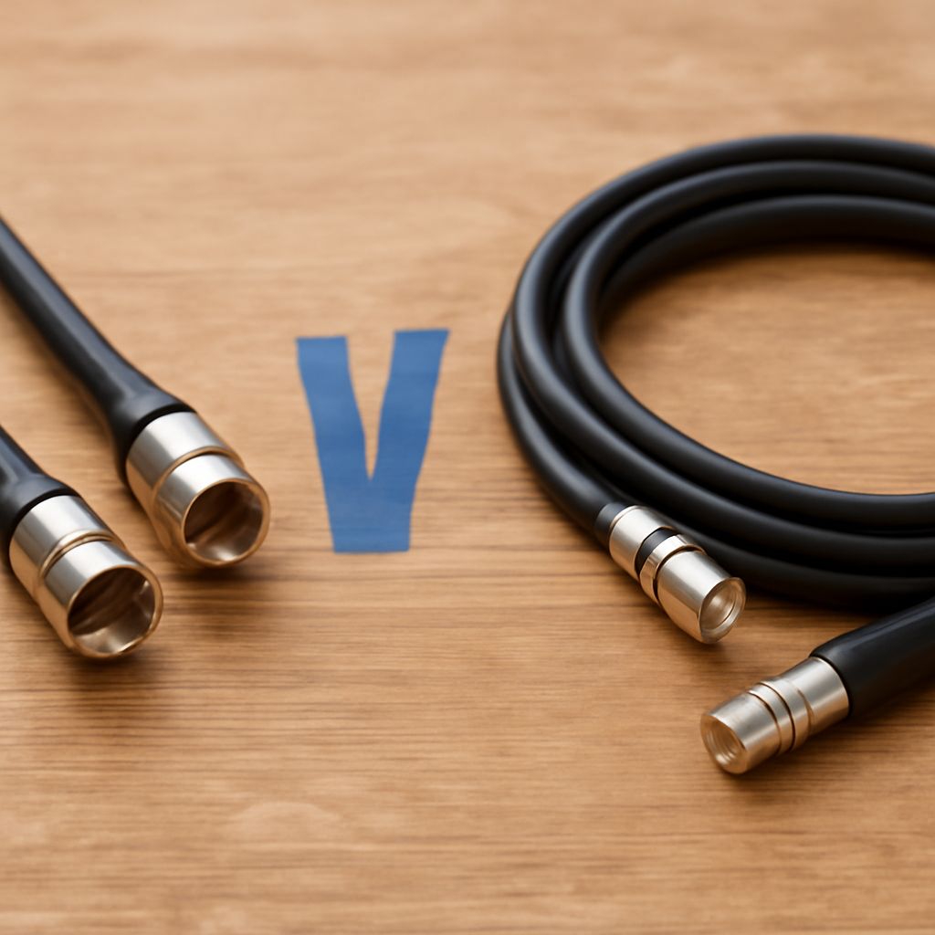
Choose a coax cable connector only after identifying the signal, impedance, frequency range, and required run length. For most residential television and cable-internet installations, that means 75-ohm RG6 cable with a properly fitted F connector. HDMI is different: it is a high-speed digital video interface, so changing its plug to an F connector does not turn it into a television RF signal.
Use a cable-loss estimate to check whether the selected coax can carry the signal over the planned distance. Then match the connector and any converter to the system at both ends, rather than choosing by physical appearance alone.
How do you identify the signal before choosing a coax cable connector or converter?
Start with the source and destination. Television antenna, cable-television, satellite, and cable-modem signals normally use 75-ohm RF coax. Professional radio, wireless, and test equipment commonly use 50-ohm coax. Composite video can also use 75-ohm coax, even when it terminates in an RCA plug instead of an F connector.
Impedance is an electrical requirement, not a description of the plug. A connector may physically attach while creating an impedance mismatch that causes reflections, insertion loss, or poor return loss. Frequency and bandwidth matter too: a cable suitable for low-frequency video may perform poorly with gigahertz cable-internet or satellite signals.
HDMI adds a separate issue: signal format. HDMI carries digital audio and video using a high-speed differential interface. A passive adapter can change the physical connection, but it cannot create an RF carrier, tune a television channel, or encode HDMI into a format a coax input understands.
An active HDMI-to-coaxial converter can mean one of two products. An HDMI-over-coax extender transports the HDMI signal through coax to a matched receiver, usually with a transmitter and receiver pair. An HDMI RF modulator converts the source into a modulated television channel that compatible televisions can tune. Check the output standard, channel range, resolution, and whether a receiver is required before buying.
What are the common coaxial connector types?
The most useful coaxial connector types are distinguished by impedance, frequency capability, attachment method, and application:
- F connector: The threaded 75-ohm connector used for cable television, antennas, satellite equipment, and cable modems. Compression F connectors generally provide a more reliable installation than push-on or poorly crimped versions.
- BNC: A bayonet-lock connector used for test equipment, broadcast hardware, security video, and some network or radio equipment. BNC versions are available in both 50-ohm and 75-ohm designs, so the rating must be checked.
- N connector: A larger threaded connector commonly used for outdoor wireless, cellular, antenna, and RF systems. Most are 50 ohms, although 75-ohm versions also exist.
- SMA: A small threaded RF connector, usually 50 ohms, used on wireless modules, antennas, measurement equipment, and compact radio hardware.
- RCA: A simple push-fit connector often used for composite video. Its typical video application is 75 ohms, but the plug itself does not guarantee a particular cable or frequency performance.
Use an adapter when the signal, impedance, and frequency requirements already match and only the mechanical interface differs. For example, an F-to-BNC adapter may be appropriate in a 75-ohm video system. It is not a substitute for an RF converter, HDMI extender, amplifier, or protocol translator.
How do you use a coax loss calculator to estimate signal loss?
A coax loss calculator needs at least three inputs: the exact cable type, the signal frequency, and the cable length. Select the manufacturer’s attenuation figure at that frequency, commonly listed in decibels per 100 feet or per 100 meters. Calculate the cable loss with:
Loss in dB = rated attenuation × run length ÷ rated reference length.
For example, if a cable is rated at 6 dB per 100 meters at 100 MHz, a 30-meter run produces about 1.8 dB of cable loss. If the same cable is rated at 20 dB per 100 meters at 1 GHz, that run produces about 6 dB. The figures are representative only; use the manufacturer’s data for the actual cable.
Frequency has a major effect because coax attenuation rises as frequency increases. A run that works comfortably for an antenna channel may have much less margin at higher cable-modem or satellite frequencies. Temperature, cable age, bends, water intrusion, and poor terminations can add practical loss beyond the catalog value.
Add every passive component to the estimate:
- Connector and barrel losses, using their specifications when available.
- Splitter or tap loss, which may be several decibels per output.
- Wall plates, surge protectors, and distribution hardware.
- Extra cable length used for routing and service loops.
Compare the total with the source’s output level and the receiver’s acceptable input range. A 3 dB loss represents approximately half the signal power, while 6 dB represents approximately one-quarter. A calculator estimates attenuation; it does not prove that a network will work if the system also has noise, ingress, poor shielding, or an incompatible return path.
What is the best coaxial cable for internet and television?
The best coaxial cable for internet in most homes is 75-ohm RG6 with a solid center conductor, suitable shielding, and compression F connectors. RG6 is usually preferred over RG59 because it has lower loss at modern cable and satellite frequencies and typically provides better shielding and mechanical support. Choose cable with a frequency rating that covers the service, often up to at least 1 GHz or higher for current broadband systems.
For cable internet, use a continuous, undamaged run between the provider’s demarcation point, splitter, and modem. Avoid unnecessary splitters, very cheap push-on connectors, and copper-clad aluminum when the installation calls for a dependable solid-copper center conductor. The modem’s upstream signal also travels through the coax, so a cable that works in one direction is not automatically suitable for the complete DOCSIS path.
RG59 remains useful for short, low-frequency composite-video or older security-camera runs, but it is usually a poor replacement for RG6 in new broadband wiring. RG11 has lower attenuation over long distances, making it useful for extended outdoor or campus-style runs, but it is thicker, less flexible, and requires compatible connectors and tools.
Finally, select the connector for the cable diameter and equipment impedance. A correctly installed 75-ohm F connector on RG6 is generally the right endpoint for residential RF. If the source is HDMI, retain the HDMI connection until an active extender or RF modulator performs the required conversion; an adapter alone only changes the shape of the connection.


