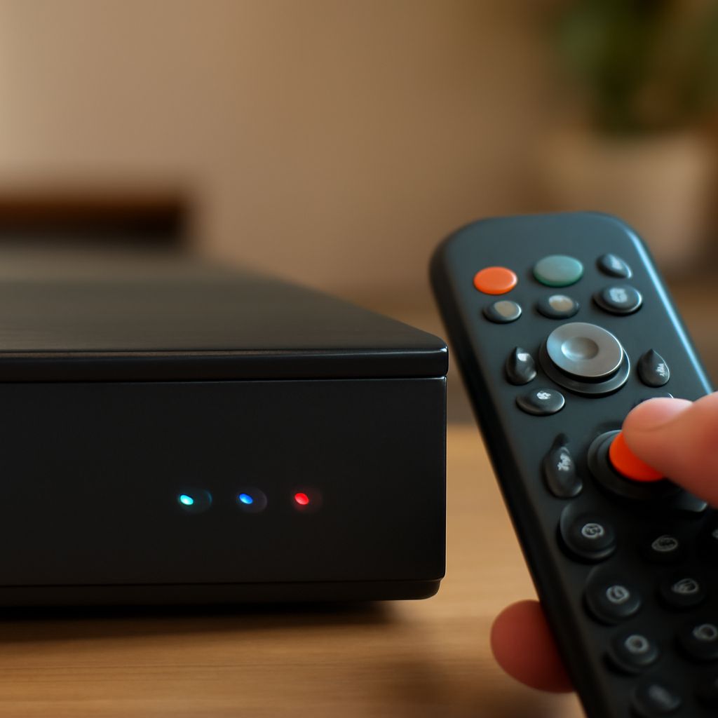
A DVR for TV antenna reception should be tested with the antenna and a short coax lead before either device is committed to a tower. This catches band, aiming, and tuner problems while every connector remains accessible.
After final mounting, preserve the proven signal path: use the same antenna orientation, quality RG-6 coax, weatherproof connectors, and as few splitters as possible before completing a fresh scan and recording test.
DVR for TV antenna: which tuner and antenna fit your channels?
Start with a local coverage map or broadcast database and list each station’s physical RF channel, direction, and estimated signal strength. Do not choose by virtual channel number alone. A station displayed as channel 5, for example, may transmit on a different physical frequency.
Match the antenna to those RF bands. VHF-low, VHF-high, and UHF require different element designs, so a UHF-only antenna can miss a VHF station even when that station appears prominently in your channel guide. A directional antenna generally provides more gain when stations are clustered in one direction. A multi-directional model is more convenient when towers are widely separated, but can have less usable gain and more multipath interference.
Choose an OTA DVR with a compatible tuner, a 75-ohm antenna input, and enough tuners for the recordings you expect to make simultaneously. Confirm that the DVR can scan physical channels and schedule recordings from the received guide. If the antenna includes an amplifier, plan for its power inserter and place it where the manufacturer specifies.
How do you install a TV antenna and test the DVR before tower mounting?
Before tower work, install a TV antenna temporarily at an accessible height, clear of large metal objects and building obstructions. Use the exact antenna, DVR, power supply, and approximate coax route that the finished system will use.
- Connect the antenna directly to the DVR with a short, known-good RG-6 cable. Do not add a splitter during the first test.
- Power the preamplifier, if fitted, and run a full channel scan. Record signal strength or quality readings, not merely the number of channels found.
- Rotate a directional antenna in small increments toward the best station group. Check the weakest important channel after each adjustment and mark the winning orientation.
- Schedule a short recording on a marginal channel, let it finish, and play it back. Confirm that audio, video, and timestamps remain stable.
A successful indoor scan is not proof that a changed long coax run and splitter path will perform identically. The tower’s height may improve reception, but added cable loss, connectors, and distribution hardware can also reduce the margin.
How should you plan a home antenna tower, mount, grounding, and coax route?
Treat a home antenna tower as a structural installation, not simply a taller mast. Add the antenna’s projected wind area, mast length, brackets, rotor, ice load where applicable, and cable weight to the support calculation. Use a tower, roof mount, or tripod rated for that combined load and for the local wind conditions. A guyed mast needs properly positioned anchors and tensioned guy wires; a roof mount needs sound framing rather than only roofing material.
Keep the antenna and mast clear of overhead power lines during assembly and in the finished position. Follow the support manufacturer’s required setbacks, fasteners, and maximum unsupported mast length. If the proposed height or wind exposure exceeds the mount’s rating, use a stronger support or obtain structural advice before climbing.
Plan the coax route before raising the antenna. Use one continuous RG-6 run where practical, support it independently of the antenna connector, avoid crushing or tight bends, and keep it separated from parallel electrical wiring. Leave a downward drip loop before the cable enters the building, and seal the wall penetration after the cable is positioned.
Provide two grounding interfaces: a listed clamp for the metal mast or tower, and a coax grounding block on the incoming feed before it enters the house. Bond both to the building’s grounding electrode system using the required conductor and approved clamps; do not improvise with an isolated ground rod or an unlisted connection. A tower may require additional bonding and grounding, so follow local electrical requirements and the tower manufacturer’s instructions.
How do you weatherproof the coax, manage splitter loss, scan channels, and verify recordings?
Use outdoor-rated compression F connectors and make sure the cable’s dielectric and braid are prepared to the connector manufacturer’s dimensions. At every exterior connection, tighten the connector correctly, then cover it with a weatherproof boot or self-amalgamating tape. Seal the cable entry and keep water flowing away through the drip loop rather than toward the connector.
Account for distribution loss before adding an amplifier. A two-way splitter typically costs about 3.5 to 4 dB, a three-way model about 5 to 6 dB, and a four-way model about 7 to 8 dB, before coax and connector losses. Use the fewest outputs needed and choose a low-loss splitter. Add a distribution amplifier only after confirming that the antenna signal is clean; amplification cannot restore a poor aim and can overload a tuner when strong stations are present.
After the antenna, coax, grounding block, and splitter are permanently installed, connect the DVR and run a new full scan. Delete or replace the earlier channel list so the guide reflects the final path. Test the weakest priority station live, then schedule a recording on it and on a stronger station. Play both files back after completion, checking for pixelation, audio gaps, recording duration, and correct channel data.
If a final scan loses channels, temporarily bypass the splitter, inspect each F connector for braid contact or a loose center conductor, and compare the DVR’s readings with the temporary test. Correct the physical signal path before changing the antenna aim or adding gain.


