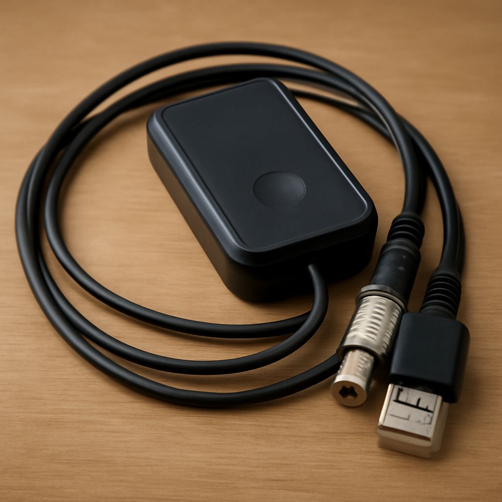
An ATSC TV tuner receives broadcast signals from an antenna, decodes the RF channels, and sends the resulting programs to a television or display. For a UHF setup, connect a UHF-capable antenna to the tuner with 75-ohm coax, scan for channels, and check the unamplified path before adding gain.
If the direct connection is stable, an amplifier is unnecessary. If cable length, splitters, or a weak antenna signal cause dropouts, add only enough gain to overcome those losses without overloading the tuner.
How does an ATSC TV tuner receive UHF channels?
The tuner input receives an over-the-air RF signal, usually through an F-type jack. It selects a physical RF channel, demodulates the ATSC broadcast, and maps that signal to the virtual channel number shown in the program guide. A station listed as virtual channel 5, for example, may actually use a different UHF RF channel.
Confirm that the antenna covers the band you need. A UHF-only antenna is suitable for UHF stations, while a combined VHF/UHF antenna is needed when local stations use both bands. An antenna’s advertised range, direction, and installation height also affect reception, but amplification cannot compensate for an antenna that does not cover the required band or is aimed poorly.
For an initial test, connect the antenna directly to the tuner with one known-good cable. Avoid the splitter and amplifier until you know how many channels the basic path can receive.
What is a UHF connector, and does it fit a TV coax path?
The phrase UHF connector commonly refers to the PL-259 plug and SO-239 socket, not to the F connector normally used on television equipment. A PL-259 may appear on some radio or specialty antenna hardware, while a TV tuner generally expects an F connector and 75-ohm coax.
Use RG6 or another properly rated 75-ohm coaxial cable between a standard antenna output and the tuner. The cable should have an F male connector at the antenna and tuner ends when both devices provide F female sockets. A connector must match both physically and electrically: a PL-259-to-F adapter may make the parts connect, but it does not automatically create the correct 75-ohm path.
If the antenna provides 300-ohm twin-lead terminals, install a suitable 300-to-75-ohm balun before connecting coax. Keep outdoor connections weatherproof, and replace loose, corroded, or damaged connectors before diagnosing weak reception.
When does a UHF amplifier help, and where should it go?
A UHF amplifier helps when the antenna signal is usable but losses in the distribution path reduce it below the tuner’s reliable operating range. Common losses include long coax runs and splitters. A typical two-way splitter introduces about 3.5 dB of loss, while a four-way splitter introduces about 7 dB, before cable loss is added.
- Preamplifier: Install it close to the antenna, before a long cable run. This placement preserves a weak signal before cable noise and loss accumulate. The amplifier may require a power inserter indoors.
- Distribution amplifier: Install it indoors after the incoming coax and before the splitter. It is useful when the antenna-to-building signal is already adequate but several tuner outputs share the loss.
Compare amplifier specifications rather than choosing the highest gain. Gain, measured in decibels, should roughly cover the cable and splitter loss with modest reserve. A low noise figure is important for a weak signal because the amplifier adds less noise relative to the incoming signal. A preamplifier with excessive gain can be worse than no amplifier.
Strong local stations can overload an amplifier or the tuner front end. Symptoms include missing channels, unstable decoding, or worse reception after amplification. If the direct path already produces stable channels, leave the amplifier out. If gain is adjustable, start at its lowest useful setting.
How do you rescan and compare channel quality?
- Connect the antenna directly to the tuner with the shortest practical 75-ohm coax path. Position the antenna consistently, then run a complete channel scan.
- Record the physical RF channels found and note each station’s signal strength, signal quality, and dropout behavior. Quality and decoding errors are more useful than strength alone.
- Reconnect the splitter or long cable without amplification and scan again. The difference shows the distribution loss. Check every connector if channels disappear unexpectedly.
- Install the appropriate preamplifier or distribution amplifier, apply power, and scan again. Compare the same channels under the same antenna position and weather conditions.
- Keep the amplifier only if quality improves or dropouts decrease. If channels vanish or quality falls, bypass it, reduce its gain, or investigate overload from strong nearby signals.
A successful setup has stable decoding through the complete intended path, not merely a higher strength reading. Stop adding gain once the tuner receives reliable channels.


