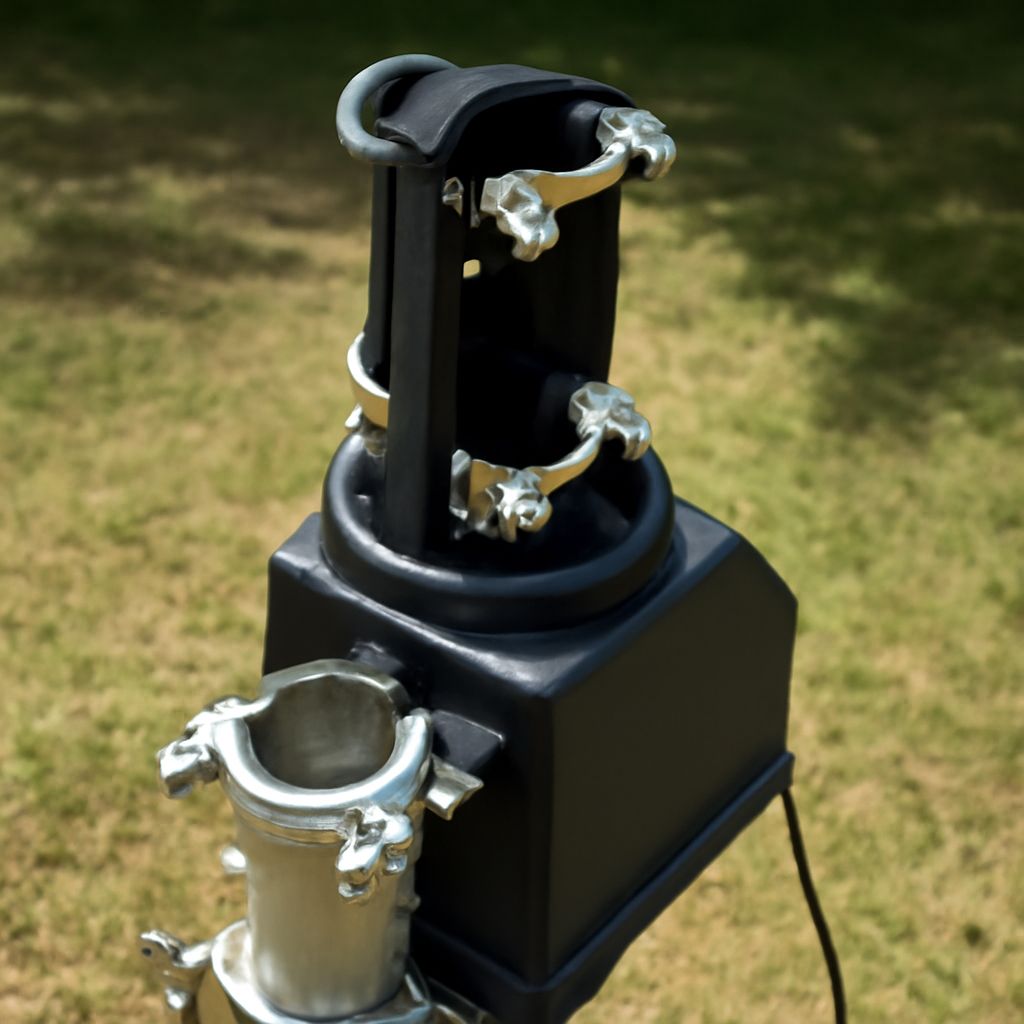
For homes where broadcast stations sit in different directions, tv antenna rotors let one directional antenna turn toward each signal source instead of using multiple antennas. Choose the unit by the antenna’s wind area, turning torque, mast diameter, and vertical load—not by antenna weight alone.
The rotator mounts between a fixed support mast and the rotating mast that carries the antenna. Before installing, confirm the rotator’s load ratings, provide enough cable slack for the full travel range, and establish repeatable headings so every station can be found again.
When Are TV Antenna Rotors Useful?
A rotator is useful when stations you want are separated by a substantial angle, such as transmitters to the north and southwest. A directional VHF/UHF antenna can provide better reception than an omnidirectional model, but it must face the transmitting site. Turning the antenna allows one installation to serve those different headings.
A rotator may be unnecessary if all important stations are in roughly the same direction or if a broad-beam antenna receives them reliably. It also adds moving parts, wiring, and aiming steps. Use one when the improvement from pointing the antenna accurately outweighs that added complexity.
- List the stations you want and their approximate compass headings.
- Check whether terrain, buildings, or trees make a precise aim more important.
- Decide whether the antenna must turn through a full circle or only between two limited directions.
What Does a TV Antenna Rotator Include?
A tv antenna rotator is a motorized housing with gears, bearings, clamps, and a control connection. The lower clamp attaches to the fixed support mast, which is secured to the roof, tower, or other structural support. The upper clamp holds a separate rotating mast section. The antenna attaches to the top of that rotating section.
The bearings carry the rotating mast and keep it aligned while the motor turns it. Clamps must match the mast diameter and be tightened evenly. Do not assume that a rotator replaces every structural component: a tall or heavily loaded mast may need a thrust bearing above the rotator so the motor does not carry excessive side load.
The indoor controller sends power and direction commands through the control cable. It normally includes a heading indicator, such as a numbered dial or electronic display. Some models have stored positions; others require you to turn the antenna while watching the indicator. Follow the manufacturer’s cable type, terminal order, grounding, and weather-sealing instructions.
How Do You Match a Rotator to the Mast and Antenna Load?
Start with the antenna’s published wind area or wind-load rating. Wind creates force across the antenna, and that force acts at a distance from the rotator. The resulting turning moment is approximately wind force multiplied by the distance from the rotator’s axis. A large antenna, a long mast, or an antenna mounted far above the rotor can therefore demand much more torque than its weight suggests.
Compare the installation with the rotator’s maximum antenna wind area, allowable turning torque, vertical load, mast diameter range, and recommended mast height. Select a model with reserve capacity for gusts rather than operating at the limit. Account for the antenna boom, elements, preamplifier, coax, clamps, and any side-mounted accessories.
Unbalanced loading matters as well. If the antenna’s center of wind area is offset from the mast, the wind produces a stronger turning moment and side force. A long rotating mast can also flex or oscillate. Use the manufacturer’s maximum rotating-mast length and diameter, and add a thrust bearing or additional support when the structure exceeds the rotator’s direct-load recommendation.
- Wind area: use the manufacturer’s rated area, not only the antenna’s physical size.
- Torque: allow for wind force multiplied by the offset distance and for unbalanced loading.
- Vertical load: include the complete rotating assembly, not just the antenna.
- Mast fit: verify both the fixed support mast and rotating mast diameters.
How Do You Wire, Calibrate, and Test the Aim?
- Install the support and rotor. Secure the fixed support mast first. Keep the rotating mast plumb, insert it to the specified depth, and tighten both clamps without crushing the tube. Confirm that the antenna clears the roof, tower, and nearby objects through its entire travel.
- Route the control cable. Connect the indoor controller exactly as marked. Leave a loose loop at the rotating joint large enough for the full specified rotation, then secure the cable to the fixed mast below that loop. The loop should bend freely without pulling on the terminals, wrapping around the mast, or rubbing against sharp hardware. Add a downward drip loop and weatherproof outdoor connections.
- Set a reference heading. Turn the rotator to its marked zero or reference position. Point the antenna at a known compass heading or landmark, then align the heading indicator with that position according to the manual. Keep the same reference system—magnetic compass readings or true headings—when recording stations.
- Check physical limits. Operate the rotator slowly across its permitted range. Stop before the cable becomes tight or the antenna contacts an obstruction. If the model has adjustable electrical or mechanical stops, set them before normal use.
- Test station headings. Aim at each transmitter heading and rescan or tune the television. Allow the receiver or signal meter a few seconds to settle, then record the heading that produces the strongest, most stable signal. Test several degrees on either side because the best heading may not match a map estimate.
Successful calibration gives repeatable results: returning to a recorded heading should restore the same stations without cable strain or unusual motor noise. If reception changes unpredictably, check that the mast is vertical, the indicator is synchronized, the coax and control connections are sound, and the antenna is not slipping in its clamp.


