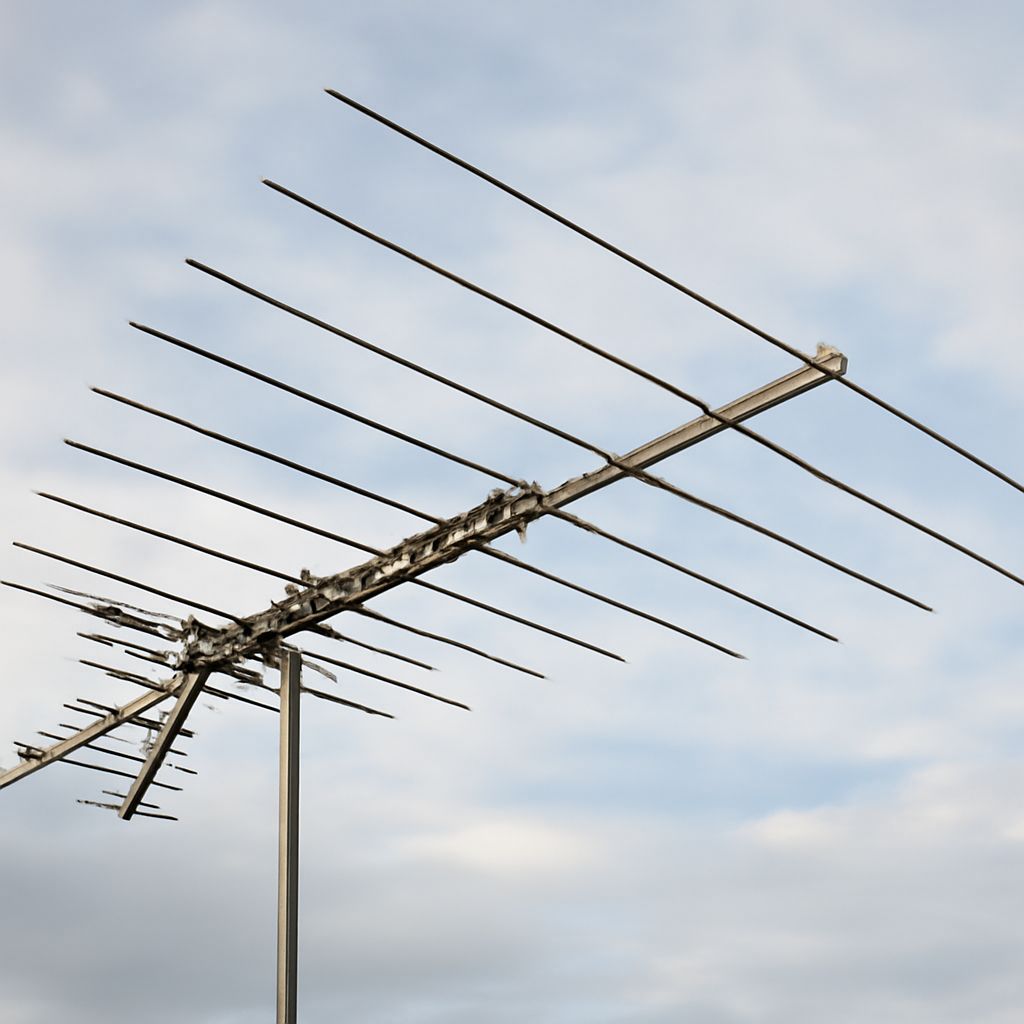
An antenna mast pole, a correctly sized antenna, and low-loss coax are the three parts that determine whether a homemade TV antenna works reliably. Start with the local channels you need, then point the antenna toward their transmitters before permanently fastening the mast.
For a practical first build, use a four-bay bow-tie design for UHF and high-VHF stations. Add a separate longer VHF element or use a combination antenna if important local stations are on low VHF channels.
Antenna Mast Pole Planning: Match Channels and Mount Securely
Check a local broadcast channel map to identify each station’s real RF channel, not only its advertised virtual channel. Channels 2–13 use VHF frequencies, while higher-numbered channels generally use UHF frequencies. Note the compass direction and distance to each transmitter. If most stations are clustered in one direction, a directional bow-tie or Yagi-style antenna is suitable. Stations spread across several directions may require a broad-beam antenna or a rotator.
Choose the mast location before building the feed line. A roof, chimney, or eave position usually performs better than a low attic or wall location, but avoid utility lines and keep the antenna clear of nearby metal, trees, and roof obstructions. Use a galvanized mast with two separated mounting points, heavy-duty brackets, and guy wires when the exposed section is tall or flexible. Keep the antenna at least a few feet above the roofline where practical, and ground the mast and coax entry according to local electrical requirements.
- Use a rigid pole that does not sway noticeably in normal wind.
- Keep the antenna elements away from the mast with a nonconductive stand-off or suitable mounting hardware.
- Leave enough clearance to rotate or adjust the antenna during testing.
- Do not work on a mast near overhead power lines.
How to make a TV antenna and connect it
A simple four-bay bow-tie antenna needs a flat wooden board, eight pieces of 14-gauge or 16-gauge copper or galvanized wire, screws or small stand-offs, and a 300-ohm twin-lead-to-75-ohm transformer, often called a balun. The dimensions favor UHF and high VHF reception; they are not a full-size solution for low VHF.
- Cut eight wire sections about 14 inches long. Bend each section into a shallow V, leaving a small gap at the point.
- Mount four pairs on the board, spaced about 7 inches apart vertically. Each pair should form a bow tie, with the open tips facing outward.
- Connect the left arms of all four bow ties together and the right arms together. Keep the two sides electrically separate.
- Attach the balun’s two terminals across that center gap. Connect the balun’s F-connector to the coaxial cable.
- Add a wire-mesh reflector 2–4 inches behind the elements if signals are weak and primarily arrive from one direction. The reflector faces away from the transmitters.
Inspect every joint for a short between the two feed terminals. Seal outdoor wire connections with self-fusing rubber tape followed by UV-resistant electrical tape or an outdoor coax seal. Mount the finished antenna so its broad face points toward the transmitter group. If you need low-VHF channels, use longer elements sized for those frequencies or install a purpose-built VHF/UHF antenna rather than expecting short UHF elements to receive them well.
How to choose the best coaxial cable for a TV antenna run
The best coaxial cable for a TV antenna depends on distance, signal strength, and interference. For most installations, use 75-ohm RG6 with a solid polyethylene dielectric and compression F-connectors. RG6 generally has lower loss than RG59, especially on UHF frequencies. A short run under about 50 feet can use good-quality copper-clad-steel RG6; a long run, weak-signal location, or powered preamplifier favors solid-copper RG6.
- Choose standard RG6 for ordinary indoor or outdoor runs.
- Choose quad-shield RG6 when the cable passes near strong sources of radio-frequency interference; shielding cannot compensate for poor antenna placement.
- Use outdoor-rated, UV-resistant cable on the mast and roof.
- Do not sharply kink the cable. Maintain at least a 3-inch bend radius, or follow the cable maker’s larger specification.
Install a compression connector rather than a twist-on type. At the antenna, point the cable connector downward where possible and form a small drip loop before the cable enters the building. Seal the outdoor connector and any ground-block connection against water, but do not crush the cable under staples or tight clamps. Keep the run as short and direct as practical, with no unnecessary splitters.
Aim, scan, and refine the installation
- Connect the antenna directly to the television or converter box, bypassing splitters and amplifiers during the first test.
- Loosen the mast or antenna clamp just enough to permit controlled movement.
- Point the antenna toward the strongest transmitter group and run a complete channel scan.
- Rotate it 5–10 degrees at a time, scanning after each movement. Record channels that appear, disappear, or become pixelated.
- Choose the direction that provides the most stable reception for the channels you actually watch, not merely the highest single signal reading.
After finding the best direction, repeat the scan with the antenna fully tightened. Check reception at different times and on windy days. If one direction works for UHF but loses VHF, adjust for the weaker band or add the appropriate VHF element. If the picture breaks up only after a splitter or long cable is connected, address feed loss before changing the antenna. Finally, secure every mast bracket, weatherproof the connectors, and run one last channel scan.


