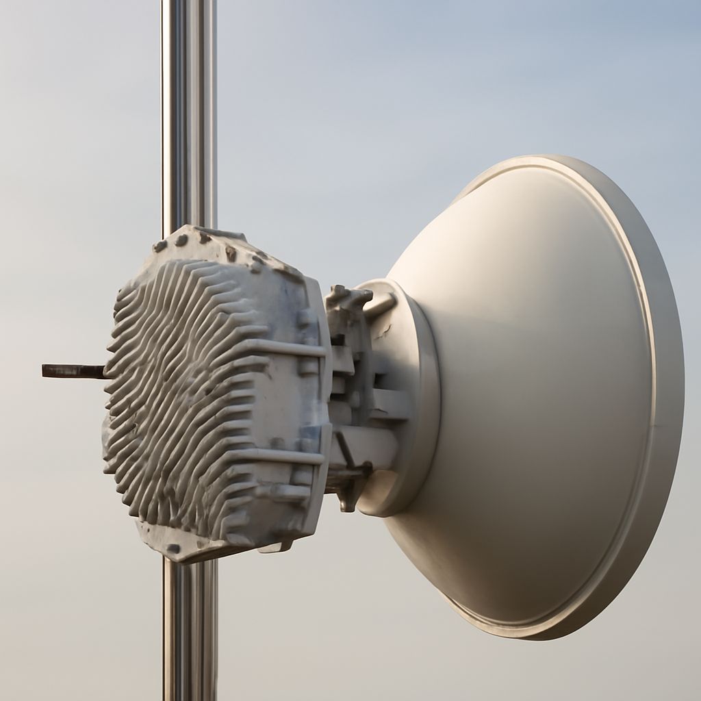
A long-range Wi-Fi antenna for 5 miles is not enough by itself. For a reliable five-mile connection, plan two outdoor radios as a single RF path: confirm terrain and Fresnel clearance, choose directional antennas, control interference, then align and measure throughput. A point-to-point wireless network can work across this distance, but a visible horizon alone does not prove that the path is usable.
Begin with the capacity requirement. A link carrying occasional file access can use different radio settings from one carrying video, voice, or multiple office networks. Set a target for aggregate throughput, latency, and availability before selecting hardware.
Is a long-range Wi-Fi antenna for 5 miles enough by itself?
No. Antenna gain improves the link budget, but it cannot remove an obstruction, correct a noisy channel, or compensate for inaccurate alignment. A five-mile design needs compatible radios at both ends, outdoor-rated mounting, stable power, and antennas aimed at each other.
Use the link budget to check whether the expected received signal has enough margin:
- Transmit power: use the radio’s permitted output, not simply its maximum setting.
- Antenna gain: high-gain dishes or narrow panels concentrate energy and reduce unwanted reception from the sides.
- Cable and connector loss: long coax runs can erase the benefit of a high-gain antenna. Mount the radio close to the antenna or use short, low-loss cable.
- Noise margin: compare predicted receive level with measured noise, not with a sensitivity figure alone.
Use a dedicated bridge mode for the fixed link. Unlike a client Wi-Fi network, which connects many nearby devices to an access point and may support roaming, a point-to-point bridge connects two fixed LANs over one directional RF path. That distinction affects antenna choice, channel width, addressing, and alignment.
How do path profile, Fresnel zone, mounting height, and weather determine clearance?
Build a path profile using the exact endpoint coordinates, ground elevations, and proposed antenna heights. Include trees, buildings, ridges, cranes, and other structures. Model vegetation at full seasonal height; a path that clears bare winter trees may fail when leaves are present.
Line of sight is only the first check. Radio energy occupies a three-dimensional area called the first Fresnel zone. Obstructions inside it can reflect or absorb energy even when the antenna tips appear visible. Aim for at least 60% clearance of the first zone along the path, with extra margin for uncertain terrain or moving foliage.
At the midpoint of a five-mile path, the first Fresnel radius is roughly 36 feet at 5 GHz and 52 feet at 2.4 GHz. The required mounting height therefore depends on more than the tower or roof height: add the obstruction elevation, the required Fresnel clearance, and the effect of earth curvature. A path tool that uses a standard atmospheric refraction model can estimate the combined profile.
Mount each radio on a rigid structure that will not twist in wind. Account for roof vibration, tower loading, lightning protection, and safe access before finalizing height. Rain has a greater effect as frequency rises, while wet radomes, snow, and wind-driven movement can affect any band. Leave fade margin rather than designing for the exact predicted receive level.
How does a point-to-point wireless network differ from client Wi-Fi when choosing radios, directional antennas, and polarization?
Choose a matched pair of outdoor bridge radios designed for the selected band and distance. Integrated dish or panel radios usually reduce cable loss and simplify alignment. A narrow beam provides more gain and rejects side interference, but it also demands more accurate aiming than a broad panel.
Use the same polarization at both ends—vertical with vertical or horizontal with horizontal—unless the radio and antenna system explicitly supports another arrangement. A polarization mismatch can cause major signal loss. Keep antennas clear of nearby metalwork, rails, roof edges, and mounting brackets that can distort the beam.
Do not select the widest channel automatically. Wider channels can increase peak capacity but collect more noise and leave fewer usable channels. Start with a conservative width, often 20 MHz in a crowded environment, then expand only if a spectrum scan and throughput test justify it. Confirm that the selected frequency, output power, and antenna gain comply with local rules.
Configure one end as the bridge access point and the other as the station, with matching security, channel, country settings, and firmware. Keep management access separate from the carried traffic where practical. Use weatherproof Ethernet, proper grounding, and surge protection so a good RF design is not undermined by an outdoor installation failure.
How can microwave interference with Wi-Fi affect channel choice, alignment, and acceptance tests?
Inspect the spectrum at both ends before fixing the channel. A microwave oven is a nearby source of interference around 2.4 GHz, especially when shielding is poor or the radio is installed indoors nearby. Other access points, wireless cameras, cordless devices, and neighboring bridges may create continuous or intermittent noise. Microwave interference with Wi-Fi is usually a local 2.4 GHz problem; it does not automatically explain poor performance on a clear 5 GHz path.
Use a spectrum analyzer or the radio’s scan function during busy periods, and repeat the scan at different times. Prefer the quietest non-overlapping channel, avoid strong adjacent signals, and treat automatic channel changes cautiously on a fixed bridge. On some 5 GHz equipment, DFS channels can change after radar detection, so verify the behavior before using them for a critical link.
Align both ends mechanically, then refine the aim while watching live receive signal and noise. Peak signal is not the only goal: a slightly lower signal with substantially lower noise can deliver better modulation and throughput. Check alignment in both directions because a loose bracket or asymmetric antenna pattern can hide a problem.
Use these acceptance checks before handing over the link:
- Signal: confirm both radios report levels near the design prediction and that the readings remain stable after tightening mounts.
- Noise and SNR: record the noise floor on the selected channel and verify adequate signal-to-noise margin under normal local activity.
- Link rate: confirm the radios hold the intended modulation rather than repeatedly dropping to a lower rate.
- Throughput: run bidirectional TCP tests, then compare the result with the equipment’s expected real-world rate. Test at the required load, not only with an idle link.
- Reliability: check latency, packet loss, retransmissions, and performance during wind or rain. A useful baseline includes several hours of monitoring, with longer observation for a business-critical connection.


