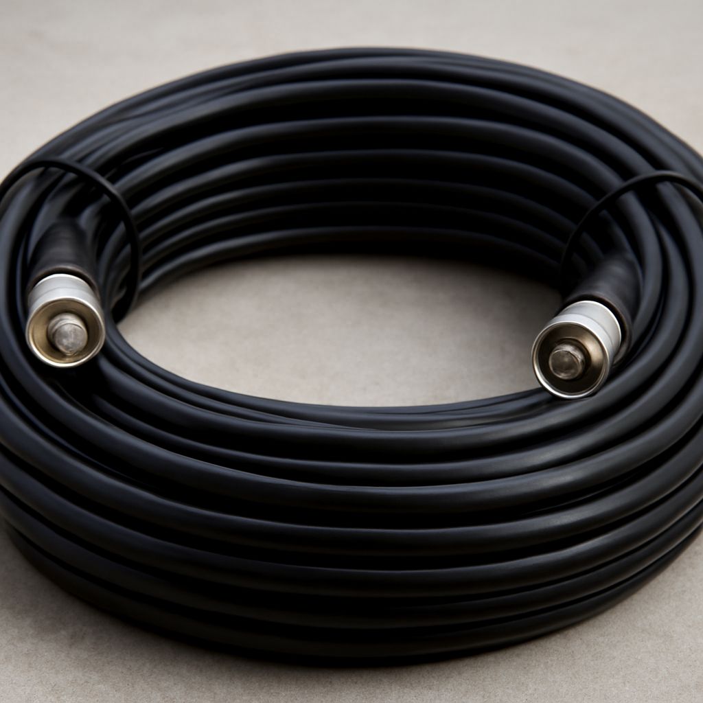
Choose a 50 ohm coax cable for most radio, RF, antenna, and test-equipment systems; choose a 75 ohm coax cable for most television, video, CCTV, satellite, and broadband distribution systems. A coax cable tracer can identify which panel port connects to an unknown wall outlet, but tracing does not prove that the run is suitable for the signal.
First identify the equipment and signal path, then confirm the cable. Connector shape alone is not enough: two coax cables may accept the same connector while having different impedance, loss, shielding, or signal-format requirements.
Why does 50 ohm coax cable impedance matter?
Characteristic impedance is the cable’s intended ratio of voltage to current for a traveling signal. It is not the same as the resistance measured with a basic ohmmeter. The source, cable, and load should normally share the same impedance so the signal reaches the load with minimal reflection.
Connecting a 50-ohm source to a 75-ohm cable, or the reverse, can create an impedance mismatch. At low frequencies and over short runs, a system may appear to work, but reflections can reduce power transfer, increase standing-wave ratio, create video artifacts, or lower data reliability. The impact becomes more important with higher frequencies, longer cables, wider bandwidth, and transmitted power.
- Impedance: Match the cable to the equipment specification, not merely to the connector.
- Loss: Compare attenuation at the operating frequency and cable length. Diameter, dielectric, shielding, and construction often matter as much as impedance.
- Signal format: A cable that fits mechanically may still be wrong for RF power, composite video, SDI, satellite IF, or another signal type.
Where do 50 ohm and 75 ohm coax systems belong?
Use the system’s documentation as the deciding factor. These are common patterns, not rules for identifying an unknown run:
- 50-ohm systems: Two-way radio, amateur radio, cellular and wireless infrastructure, Wi-Fi test setups, RF generators, spectrum analyzers, antenna feeders, and some legacy data networks. Common families include RG-58, RG-8, RG-213, LMR-240, and LMR-400. N, SMA, TNC, UHF, and some BNC connectors are commonly used.
- 75-ohm systems: Over-the-air television, CATV and broadband distribution, satellite receivers, CCTV, composite video, and digital video such as SDI. RG-6, RG-59, RG-11, and video-specific cables are common families. F connectors, RCA connectors, and 75-ohm BNC connectors are typical.
- Connector differences: F and RCA are strongly associated with 75-ohm applications, while SMA is generally 50 ohms. N and BNC connectors exist in both impedance versions. A BNC plug can fit a BNC jack without proving that the cable and equipment belong in the same signal chain.
- Loss differences: A larger RG-6 or RG-11 cable may have less loss than a thin RG-59, while a larger LMR cable may outperform RG-58. Use manufacturer attenuation specifications at the actual frequency instead of judging by cable family or diameter alone.
How can you identify coax before connecting equipment?
Identify the run while it is disconnected from transmitters, amplifiers, power injectors, splitters, and receivers. Never connect an unidentified cable to transmitting or powered distribution equipment merely because a tracer finds its far end.
- Record the starting point. Note the room, wall plate, rack position, patch-panel port, and any existing label. Photograph the connection before removing it.
- Read the jacket markings. Look for an RG designation, manufacturer part number, impedance marking, voltage rating, shield description, and footage marks. A printed 50-ohm or 75-ohm specification is more useful than appearance.
- Inspect the construction. Compare diameter, shielding, connector type, connector gender, center conductor, and bend radius with known cable. These clues can narrow the possibilities but cannot replace jacket data or documentation.
- Check for adapters and junctions. An F-to-BNC adapter, barrel, wall plate, splitter, or balun may hide the cable’s original connector and may introduce a separate impedance or signal-format issue.
- Use a meter only for basic faults. With both ends isolated, check for an open center conductor, an open shield, or a short between center and shield. Continuity does not establish characteristic impedance, shielding quality, frequency response, or acceptable loss.
How do you use a coax cable tracer to map endpoints?
A tracer performs continuity mapping when its generator and probe or remote terminator identify the same physical run. That is different from live signal testing, which checks whether the cable carries the required RF or video signal at an acceptable level.
- Isolate the run. Disconnect both ends from active equipment and remove the cable from splitters, taps, amplifiers, and power inserters when practical. Confirm that no DC voltage or transmitter output is present.
- Connect the generator. Attach the tracer’s tone generator or mapper to one end using the correct coax adapter. Do not force a connector or inject a tone into equipment that remains powered.
- Search the far end. At the patch panel, ceiling space, or room outlets, use the inductive probe or touch each cable with the tracer. With a remote-ID mapper, attach the appropriate terminator and look for the matching number.
- Handle multiple results carefully. Several responding ends may indicate a splitter, bridged outlets, a shared shield path, or an unisolated circuit. Disconnect branches and test again until one endpoint responds.
- Verify and label. Repeat the test from the identified endpoint when the tool supports two-way verification. Label both ends with the same cable ID and record the route, panel position, cable markings, and any junctions.
- Test the live signal separately. After the cable identity and impedance are confirmed, reconnect it and use the appropriate instrument: a cable analyzer or time-domain reflectometer for cable faults, an RF meter or network analyzer for RF systems, or a video and signal-level tester for video distribution.


