For clearer reception, place an antenna for FM radio where the signal is strongest and rotate an AM loop or the radio’s internal ferrite rod for the best AM sound. An antenna designed for both AM and FM may use separate elements and connections for each band, so match each one to the receiver before buying.
AM FM Antenna Choices Start With Two Different Bands
AM and FM broadcasts occupy very different frequency ranges. In the United States, the familiar AM broadcast band is around 530–1700 kHz, while FM broadcasts are around 88–108 MHz. An antenna responds to an electromagnetic signal; its size and construction affect how well it picks up a given range. That is why a compact AM loop and an extended FM dipole can perform different jobs even when they sit beside the same receiver.
A product described as an AM FM radio antenna may include an AM loop and a separate wire for FM. Look at the included elements and instructions, rather than judging compatibility from the product name alone. A package may improve both bands, but its AM element still needs a suitable AM input or a supported way to couple to the radio.
Choose and position the FM element
An indoor dipole has two conductive arms, often supplied as a T-shaped wire. Extend the arms and try the assembly near a window or an outside wall. Move it in small steps and change its orientation while listening to the same weak station. Signals can arrive by more than one path after bouncing off buildings; moving the wire can change how those paths combine at the receiver.
An outdoor FM aerial can be worthwhile when indoor locations remain noisy or the desired station is distant. It can get above some obstructions and away from indoor electronics, although local terrain and the station’s signal still matter. Consider the cable route and connector before installation; a long cable also loses some signal. Keep outdoor equipment clear of power lines and follow local grounding requirements or hire an installer.
If a portable uses a telescoping rod, extend it and adjust its angle and the radio’s position. Some devices use the headphone cord as the receiving element; their instructions will identify it. A powered antenna may amplify noise along with the station, so compare placement first.
Give AM its own test
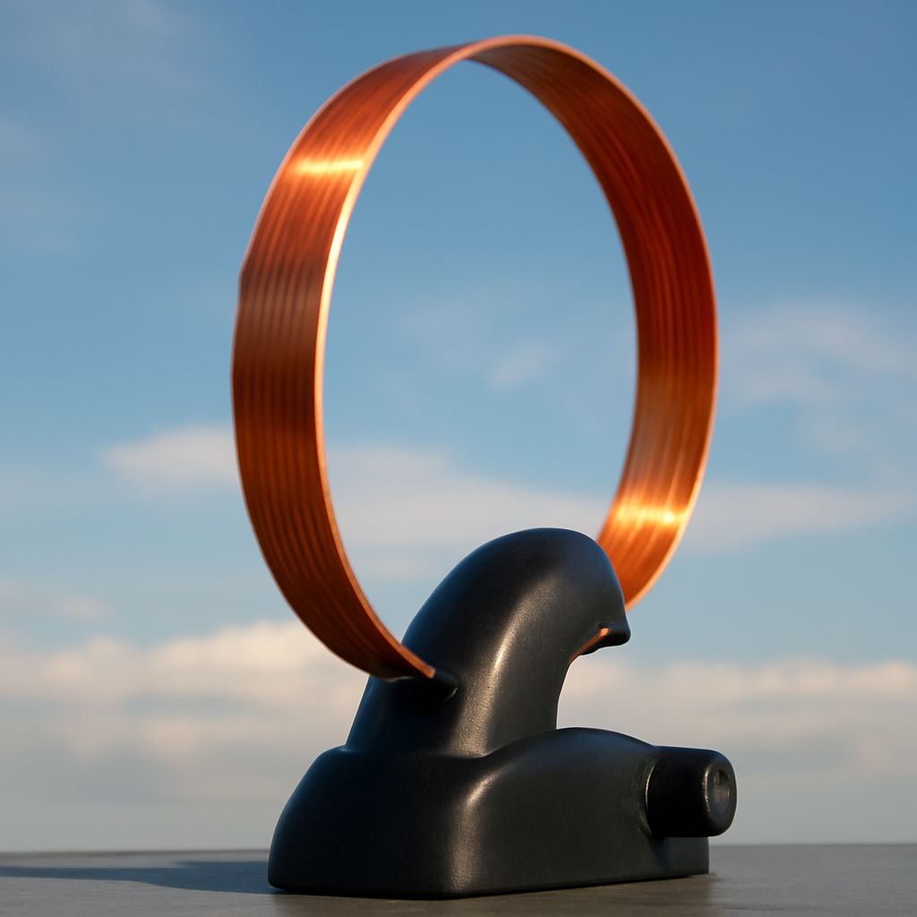
A loop consists of turns of wire arranged to pick up the AM signal. A ferrite antenna uses a coil around a ferrite rod, often built inside a portable radio. Both respond to direction: slowly rotate the loop or the entire portable and listen for the clearest result. The best direction may be the one that reduces a competing station or local buzz, even if the desired station sounds slightly louder in another position.
Place an external loop away from the receiver, power supplies, and other electronics. Sony’s connection guide recommends this separation to reduce noise pickup. Some add-on loops work by inductive coupling: set the loop near the radio’s internal antenna and adjust its tuning control if supplied. Follow the loop’s instructions, because a passive loop used this way does not require a wired antenna jack.
Match the receiver before connecting
Examine the labels and the manual with the power disconnected. One receiver may have an FM coaxial socket and separate AM spring terminals; another may have only internal antennas. Sony’s illustrated example shows separate connections for its supplied wire and loop. That layout is an example, not a universal connector standard.
Check the input type and impedance specified for an external FM reception antenna, and use the connector or adapter specified for that receiver. An adapter changes the physical connection; it does not turn an antenna for one band into a suitable antenna for both. An AM/FM radio antenna with two leads may need each lead connected to its matching input. If the radio has no external input, use its built-in element or an accessory expressly designed to couple to it; do not attach bare wire to an unrelated socket.
Compare locations and track interference
Use the same station, volume, and listening position for each comparison. Pick a weak but audible station on each band, then record a baseline: steady sound, hiss or buzz, and whether reception fades. Test one change at a time:
- Move the antenna for FM stations from an interior position to a window, then rotate it. Note the best spot and orientation.
- Move the AM loop away from electronics and turn it slowly through a full circle. For an internal ferrite rod, rotate the radio instead.
- Switch nearby chargers, LED lamps, computers, or other suspected devices off one at a time. If the buzz changes with one device, move the antenna farther away or address that source.
- Return to the first position to check that the improvement repeats. Try another station on each band: the best direction can differ by transmitter.
An AM FM antenna for radio may need two independently chosen positions, even if its components were sold together. For FM, a steady hiss can point to a weak signal, while distortion that changes as the antenna moves can reveal reflections. AM buzz that follows a nearby device points toward local electrical interference. These clues guide the next test; listening at the same time of day also helps make AM comparisons fair.
Start now: tune a weak station, mark your current position, and test the antenna in three locations. Keep the clearest result and write down its orientation so you can return to it.