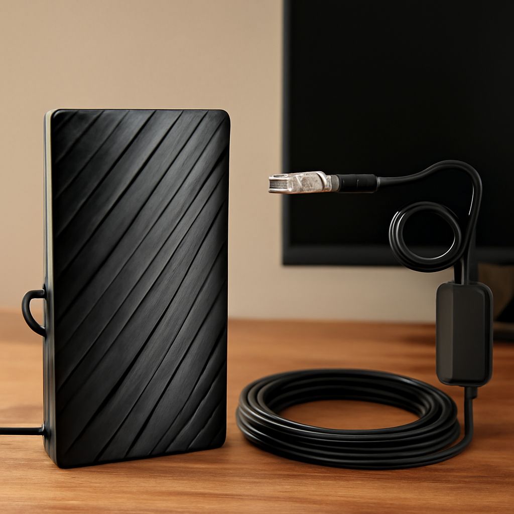
To boost your TV antenna signal, start by mapping station bearings and scanning with the antenna you already have. Choose an omnidirectional design only when local transmitters occupy several compass directions; if most stations lie in one sector, a directional antenna usually delivers more usable gain.
An omnidirectional HDTV antenna is designed for broad horizontal azimuth coverage, not equal gain at every angle or elevation. It trades peak gain for coverage, so obstructions, VHF/UHF mismatch, coax loss, or overload can still make one station reliable and another fail.
How to boost your TV antenna signal: start with bearings and a scan
Check the actual compass bearing from your antenna location to each transmitter using a local station map or coverage tool. Record the physical RF channel, not just the virtual channel number shown on the TV.
- Scan first. Connect the antenna directly to one television, remove the splitter, and run a complete channel scan. Record which stations appear and whether each picture is stable.
- Group the bearings. Stations within one general sector favor a directional antenna. Stations spread around the compass may justify an omnidirectional pattern, especially if losing one rear-facing station is unacceptable.
- Test one change at a time. Move the antenna, rotate it, replace a cable, or add amplification, then scan again. Keep the same television and scan settings.
- Compare channels individually. For every RF channel, record signal strength, signal quality, dropouts, and whether the scan finds the station. A single “signal percentage” for all channels hides the trade-off.
Signal quality and picture stability matter more than a high strength reading. A weak but clean signal can work; a strong, distorted, or multipath-affected signal may not.
Making a TV antenna for local VHF and UHF bands: materials and limits
A basic test antenna needs 75-ohm coaxial cable, a 300-to-75-ohm balun if the elements use a balanced feed, two metal elements, a nonconductive support, a weatherproof box, and a mast clamp. Use the local physical RF channels to decide the element sizes. For a simple half-wave dipole, each arm starts at approximately 2,808 divided by frequency in MHz, measured in inches, then is trimmed during testing.
One element set will not cover VHF and UHF equally well. VHF elements are physically longer, while UHF elements are much shorter. A broadband homemade design therefore needs separate, matched element groups or a carefully designed fan or array, joined with an appropriate combiner. Randomly connecting several elements can create phase cancellation and reduce reception.
A single dipole is also not truly omnidirectional: its pattern has nulls, and its performance changes with height, nearby metal, frequency, and polarization. For broad coverage, mount matched elements symmetrically around a support and keep the feed arrangement balanced. Treat the first build as a test, then compare each local channel before adding complexity.
Choosing an omnidirectional HDTV antenna: pattern, gain, and station bearings
Choose an omnidirectional antenna when reliable stations come from substantially different bearings and are strong enough that maximum forward gain is not essential. Its broad azimuth pattern reduces the need to rotate the antenna, but its gain usually varies by frequency and direction. The pattern also changes with elevation, so “360-degree” coverage does not mean equal reception above or below the horizon.
Choose a directional antenna when stations cluster in one direction, signals are weak, or a building or hill blocks one side. Directional gain can improve the desired signal and sometimes reduce interference from behind. Check that the model covers your local VHF and UHF physical channels; a UHF-focused antenna may not adequately receive high-VHF or low-VHF stations.
How placement, coax loss, and amplification affect every channel
Place the antenna as high and unobstructed as practical. A roof or mast location generally beats an indoor or attic position, while a window-facing placement may be the best indoor option. Keep it away from metal roofing, gutters, solar equipment, large appliances, and dense building materials. Trees and nearby structures can scatter signals, so moving the antenna a few feet can matter.
Use the shortest practical run of quality RG-6 coax, avoid sharp bends, and inspect every connector. Cable loss increases with frequency, so UHF channels often suffer more than VHF channels. Splitters add loss too: a typical two-way splitter loses about 3.5 decibels per output, before cable loss is counted.
Add a low-noise preamplifier near the antenna when a long cable run or multiple splitter outputs are reducing an otherwise clean signal. An amplifier cannot restore a station blocked by terrain or fix a badly mismatched antenna. If signal strength rises but quality falls, or strong stations disappear, the amplifier may be overloaded; remove it or use less gain.
After every placement or equipment change, rescan and compare RF channel by RF channel. Keep the setup that provides stable quality across the stations you watch, rather than the one that produces the highest aggregate strength reading.


