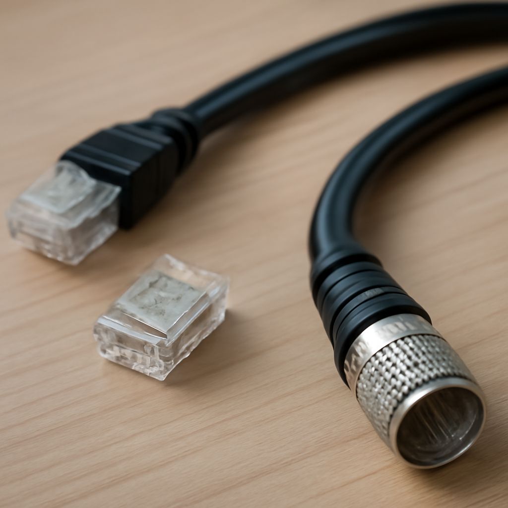
The different types of coaxial cable vary by impedance, conductor size, shielding, flexibility, and loss at a given frequency. Those differences determine whether a cable is suitable for television, RF equipment, networking, video, or digital audio.
Connector shape is a separate issue. A cable can have the right connector and still have the wrong electrical characteristics, so identify the cable family and the equipment’s required impedance before choosing an adapter or replacement.
How do different types of coaxial cable differ?
Coaxial cable contains a central conductor, dielectric insulation, conductive shield, and outer jacket. Its designation, such as RG-6 or RG-58, identifies a general cable family, but the designation alone does not guarantee a specific modern performance rating.
- RG-6: A 75-ohm cable widely used for cable television, satellite, antennas, broadband equipment, and digital video. Its thicker construction generally gives it lower loss than RG-59.
- RG-59: A flexible 75-ohm cable commonly used for short CCTV and composite-video runs. It is less suitable than RG-6 for long or higher-frequency television runs.
- RG-11: A larger 75-ohm cable with lower signal loss over long distances. It is useful for extended outdoor or building runs but is harder to bend and terminate.
- RG-58: A 50-ohm cable used in radio equipment, antennas, test systems, and legacy 10BASE2 networks. It is not a direct substitute for 75-ohm television cable.
Shielding also matters. A basic braid provides flexibility, while foil plus braid, dual-shield, and quad-shield designs offer increasing protection from radio-frequency interference. More shielding does not automatically make a cable correct for every signal; impedance, loss, jacket rating, and connector termination still need to match the installation.
What are the types of coaxial cable connectors?
These are the main coaxial connector families found in consumer, professional, and RF systems:
- F connector: A threaded 75-ohm connector used for television, satellite, cable modems, and antennas. It commonly uses the cable’s center conductor as the contact pin.
- BNC: A bayonet-lock connector available in both 50-ohm and 75-ohm versions. It is common in test equipment, broadcast video, CCTV, and RF systems.
- N connector: A larger threaded connector designed for reliable outdoor and higher-power RF applications, with 50-ohm and 75-ohm variants.
- SMA: A compact threaded RF connector, usually 50 ohms, found on wireless, cellular, GPS, and laboratory equipment.
- RCA or phono: A push-fit consumer connector used for analog audio, composite video, and digital S/PDIF audio. Its shape alone does not establish the cable’s impedance or digital suitability.
How do impedance and connector fit affect compatibility?
Impedance is the cable’s designed AC resistance to signal flow, expressed in ohms. Most television and video coax is 75 ohms, while much RF and wireless equipment uses 50 ohms. Use the impedance specified by both pieces of equipment whenever possible. A 50-ohm BNC and a 75-ohm BNC may physically connect, but that does not make them electrically interchangeable.
For a reliable installation, also check:
- Connector gender and locking method: Threaded, bayonet, and push-fit connectors require matching interfaces or a correctly rated adapter.
- Cable diameter: A connector designed for RG-6 will not necessarily crimp correctly onto RG-59 or RG-58.
- Termination quality: Loose shields, damaged center conductors, and poorly fitted compression or crimp connectors can cause signal loss and intermittent faults.
- Signal requirements: A 75-ohm digital-audio connection calls for a suitable 75-ohm cable, not merely an RCA plug that happens to fit.
Digital coaxial cable vs optical: which does your equipment support?
Digital coaxial and optical audio usually carry S/PDIF, so both can commonly transmit stereo PCM and compressed surround formats such as Dolby Digital or DTS. The source and receiver determine the actual supported formats. Neither connection normally provides the high-bandwidth formats associated with HDMI, such as multichannel PCM, Dolby TrueHD, or DTS-HD Master Audio.
- Connection: Digital coax uses an electrical RCA-style socket and should use a 75-ohm digital coaxial cable. Optical uses a TOSLINK connector, or a mini-TOSLINK plug on some compact devices, and carries light rather than an electrical signal.
- Interference: Optical is immune to electromagnetic interference and electrically isolates the devices, which can eliminate ground-loop hum. Coax can be more vulnerable to interference but is usually mechanically robust.
- Distance: Coax can support longer runs when the cable and terminations are appropriate. Optical distance depends heavily on the transmitter, receiver, and cable quality; sharp bends, crushed sections, and dirty optical ends can interrupt the light path.
- Equipment support: Choose the connection present on both devices. A coax output cannot connect directly to an optical input without an active converter, and a passive plug adapter cannot convert electrical S/PDIF into optical light.
When both inputs are available, choose optical for electrical isolation or a noisy environment, and choose digital coax for a sturdy connection or a longer practical run. In either case, verify the equipment’s format limits and use the matching cable and connector family.


