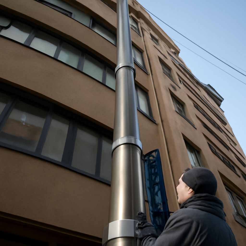
Build a telescoping antenna tower around three checks: the antenna must cover your local VHF and UHF stations, the mast must remain stable at operating height, and the coax must move without being pulled or pinched. A lowerable setup makes aiming, repairs, and seasonal inspection easier, while an over-the-air DVR turns the tested signal into recordable channels.
Use a temporary ground-level test first, then repeat the scan after the antenna is raised and locked. The final height and cable route can change reception.
How to make your own TV antenna for local VHF and UHF channels
Start with a coverage map that lists each station’s real RF channel and bearing. UHF stations generally need a compact directional antenna; high-VHF stations need longer elements, and low-VHF stations need substantially longer elements. If your market mixes bands, a purpose-built combination antenna is usually easier than one homemade design. A DIY antenna is most practical in a UHF-heavy market.
For a simple four-bay bowtie, gather eight pieces of stiff copper wire, a nonconductive support, two conductive bus bars, a reflector, and a 300-to-75-ohm balun. As a starting point for UHF, cut each wire to roughly 6 to 7 inches, bend the wires into four matching V shapes, and leave a small gap at each V tip. Mount the bays evenly, connect one side of every V to each bus bar, and place the reflector several inches behind the elements.
- Point the temporary antenna toward the station group rather than directly at only the strongest transmitter.
- Connect the balun and a short, known-good coax cable to a television.
- Rotate the antenna in small increments and record signal quality for the weakest expected channel.
A channel that appears during a scan but breaks into blocks is not a successful test. Try a different element length or spacing, or select a commercial antenna that explicitly covers the missing VHF band. Keep the finished antenna weather-resistant and mount its balun in a sealed outdoor enclosure.
Design the telescoping antenna tower: mast sections, overlap, locks, guying, and service position
Choose a mast with sections rated for the antenna’s weight and projected wind area, not just its maximum height. A small antenna can create considerable wind load when its reflector faces a gust. The mounting bracket, base, fasteners, and guy system must support the fully extended assembly.
- Sections and overlap: Follow the mast maker’s minimum overlap. Keep at least a substantial portion of every section nested; never extend a joint until its overlap mark disappears.
- Locks: Use the supplied clamps, pins, or collars at every section. Friction alone is not a reliable lock, and each section should be checked before climbing or leaving the mast raised.
- Guying: Guy the upper mast at three or four directions when the design requires it. Attach guys to structural anchors, keep them equally tensioned, and use visible markers where people may cross them.
- Service position: Install a hinge, lowering bracket, or other approved base arrangement that lets you bring the antenna down without dismantling the entire mast.
Mark both the fully lowered position and the normal operating height. Before raising, check that the antenna, rotor, guys, and coax cannot catch on a roof edge, tree, gutter, or nearby wire. Raise one section at a time, lock it, and inspect the joint before continuing.
Compare a crank-up antenna mast: wind load, cable movement, and coax slack
A crank-up antenna mast uses a winch or crank to raise nested sections, often from a hinged base. It is convenient when the antenna must be lowered regularly for service. A manually adjusted telescoping mast has fewer moving parts, but it may require more hands-on work whenever the height or antenna direction changes. Select the design whose rated height, wind load, and lowering method fit the site.
Both designs need a controlled cable route:
- Anchor outdoor-rated coax to the fixed structure, but leave a generous, smooth service loop between that anchor and the moving mast or antenna.
- Secure the coax near the antenna so its connector is not carrying the cable’s weight. Add a drip loop before the cable enters the weatherproof connection.
- Keep the loop clear of hinges, clamps, winch cables, and telescoping joints. Retraction must take up the slack without pulling on a connector or creating a pinch point.
- If a rotor is installed, leave a separate rotating loop below it and use the rotor’s travel stops. Do not let unlimited rotation twist the coax.
Operate the mast only within its specified wind rating, and lower it when conditions exceed that rating unless the system is specifically designed to remain raised. Ground the mast and install the required coax grounding block before the cable enters the house.
Connect a TV antenna DVR, then raise, aim, scan, and verify recordings
Connect the antenna to its balun, run 75-ohm coax to the grounding block, and continue to the RF input on the TV antenna DVR. Connect the DVR to the television by HDMI and complete its channel setup. Add an amplifier only when measured cable loss or a long distribution run requires one; an overloaded tuner can reduce quality rather than improve it.
- With the mast in its service position, confirm the connectors, grounding, cable loop, and locks. Perform an initial scan to identify promising channels.
- Raise the mast to operating height, locking each section and checking that the coax loop pays out freely. Do not scan only at the lowered height.
- Aim toward the station group, then scan again. If stations come from different directions, test the strongest compromise direction or use a rotor and rescan after each position.
- Review the DVR’s quality or error reading for every important multiplex. Favor stable quality over a momentary maximum strength bar.
- Record 10 to 15 minutes from the weakest reliable channel and one strong channel. Play both files back, checking for macroblocking, audio gaps, missing guide data, and tuner errors.
If the final recording fails, lower the mast and inspect the coax for a tight loop, crushed section, loose F connector, or water entry. Then retest the aim and scan. The installation is ready when channels remain stable at operating height and scheduled recordings play back cleanly.


