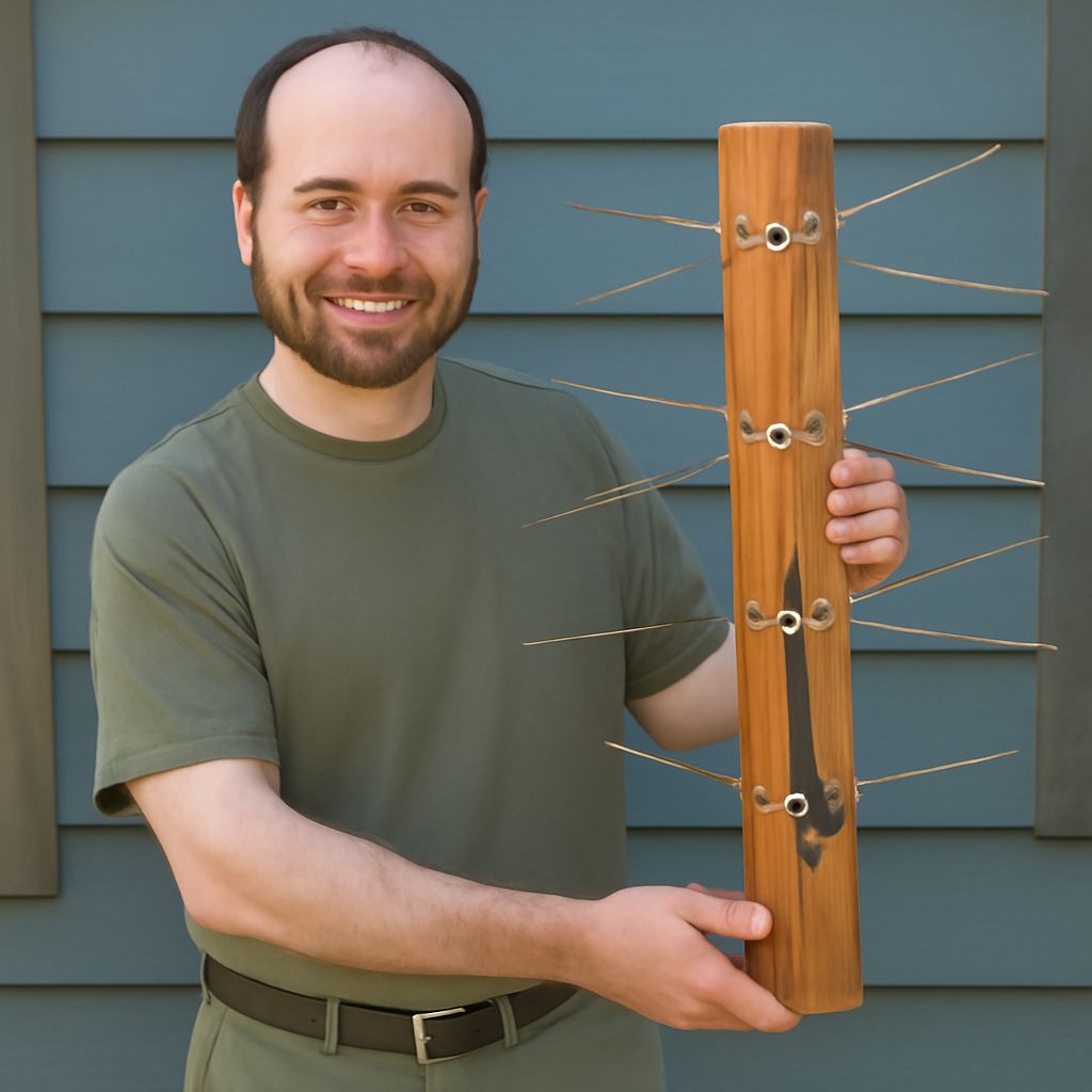
To build a TV antenna for local channels, first identify the real RF channels used in your area, then make a simple antenna that covers those bands. Test it at low height before investing time in a permanent mast. This separates antenna-design problems from height and mounting problems.
A practical DIY HDTV antenna can use a four-bay bowtie for UHF, with a separate VHF dipole when local stations broadcast on VHF. Use RG6 coax and a 75-ohm balun, and record reception before and after the final installation.
How to Build a TV Antenna for Local VHF and UHF Channels
Look up local stations by their RF channel, not only the virtual channel number shown on the television. In the United States, RF channels 2–6 are low VHF, 7–13 are high VHF, and 14 and above are UHF. A compact bowtie works well for UHF but will not reliably replace the much longer elements required for low VHF.
- UHF: Build four bowtie elements from 12- or 14-gauge copper or aluminum wire. As a starting point, make each arm approximately 2,952 divided by the channel frequency in MHz, measured in inches. For a 600-MHz signal, that is about 4.9 inches per arm.
- VHF-high: Add a dipole with arms roughly 15–17 inches long for channels near 177–195 MHz.
- VHF-low: Expect arms about 40–48 inches long for channels near 60–75 MHz. If you need this band, a compact UHF-only design is the wrong starting point.
Mount the UHF whiskers on a straight wood or PVC support, with the two feed rails separated by about 1–2 inches. A small aluminum screen 2–4 inches behind the elements can improve forward reception. Connect the rails to a 300-to-75-ohm balun, then to RG6 coax. Keep copper and aluminum joints separated with suitable hardware to limit corrosion.
Build and Test a DIY HDTV Antenna at Low Height
- Assemble the bowtie and any VHF dipole on a temporary support at roughly 6–10 feet above ground. Keep it away from fences, gutters, metal siding, and large electrical cables.
- Connect a short, known-good RG6 cable directly to the television. Do not add a splitter or amplifier during the first test.
- Point the antenna toward the group of transmitters, using a station map or compass bearing. Run the television’s channel scan and record every station that appears.
- Open the television’s signal-information screen and note signal quality, strength, and dropouts. Quality and stable video matter more than a high strength number.
Rotate the antenna in 10-degree increments and scan again if necessary. A station that appears but breaks up usually needs better aim, cleaner coax connections, or improved band coverage—not automatically a taller mast. This low-height result is your baseline for the final installation.
How to Size a DIY Antenna Mast for Diameter, Height, and Wind Load
Choose the shortest mast that clears the roofline or nearby obstruction. Galvanized steel provides more stiffness than thin aluminum; aluminum is lighter but may require a larger diameter or shorter unsupported section. For a small bowtie, 1.25–1.5-inch steel tubing with about 3–6 feet above the upper bracket is a reasonable starting range. A larger antenna, longer extension, or exposed location may require 1.5–2-inch tubing, two brackets, or guy wires.
Estimate wind demand from the antenna’s projected area, including its reflector and hardware. A useful preliminary calculation is wind pressure = 0.00256 × wind speed², with speed in miles per hour and pressure in pounds per square foot. Multiply pressure by projected area to estimate force, then account for the mast’s unsupported length: a taller antenna creates substantially more bending moment even when the antenna itself is light.
Fasten the lower bracket to structural framing, a masonry wall, or a properly installed roof mount—not just siding or trim. Keep brackets vertically separated, use corrosion-resistant bolts, and add guy wires when the unsupported section or wind area exceeds the mount’s rating. Ground the mast and coax entry according to local electrical requirements.
How to Mount, Aim, Scan, and Compare Reception
Install the antenna with its bowtie open face toward the transmitters and its reflector behind it. Leave enough clearance for rotation, and do not let the mast or mounting hardware touch the elements. Route RG6 downward in a drip loop, seal outdoor connectors, and secure the cable to the mast with loose weather-rated ties. The cable should not hang from the balun; provide a separate strain-relief loop.
Repeat the original scan at the final height and record the same measurements. Compare the low-height and final results by station:
- Improved quality and fewer dropouts: the added height or clearer line of sight helped.
- More signal strength but unchanged breakups: check aim, multipath, coax, and band coverage before adding an amplifier.
- Lost channels: inspect connectors, cable strain, and whether the mast or nearby metal is obstructing the antenna.
Keep the final mast at the lowest height that delivers stable channel quality. Height should confirm a measured reception benefit, not substitute for the correct antenna geometry and aim.


